Senior Telemaster With LED Strip Lights
Category : Model Airplane Building
The Senior Telemaster RC airplane makes a great trainer and is available many sizes: from mini all the way to a giant 12 foot wing span! With it’s slow flight characteristics and docile handling it’s truly a joy to fly – even for more experienced pilots!
Another primary advantage of the Telemaster design is its ability to be able to carry a lot of weight due to the low wing loading. This make it a great platform for modifications – as there is room to add some weight without effecting flight performance!
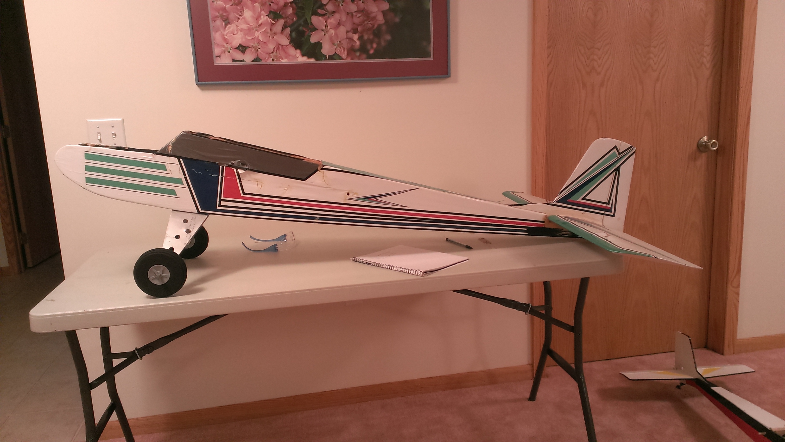
This particular Telemaster I acquired was not in very good shape and was in need of some repairs. I restored it earlier this summer: fixed the broken balsa stringers, recovered the wings, and shaped new ailerons for the wing. The fuselage was also twisted and needed to be straightened. I was able to do this by the holding the correction (twisting it past the correct point since it will naturally spring back a little) in place while shrinking the covering with an iron. I added a set of flaps!
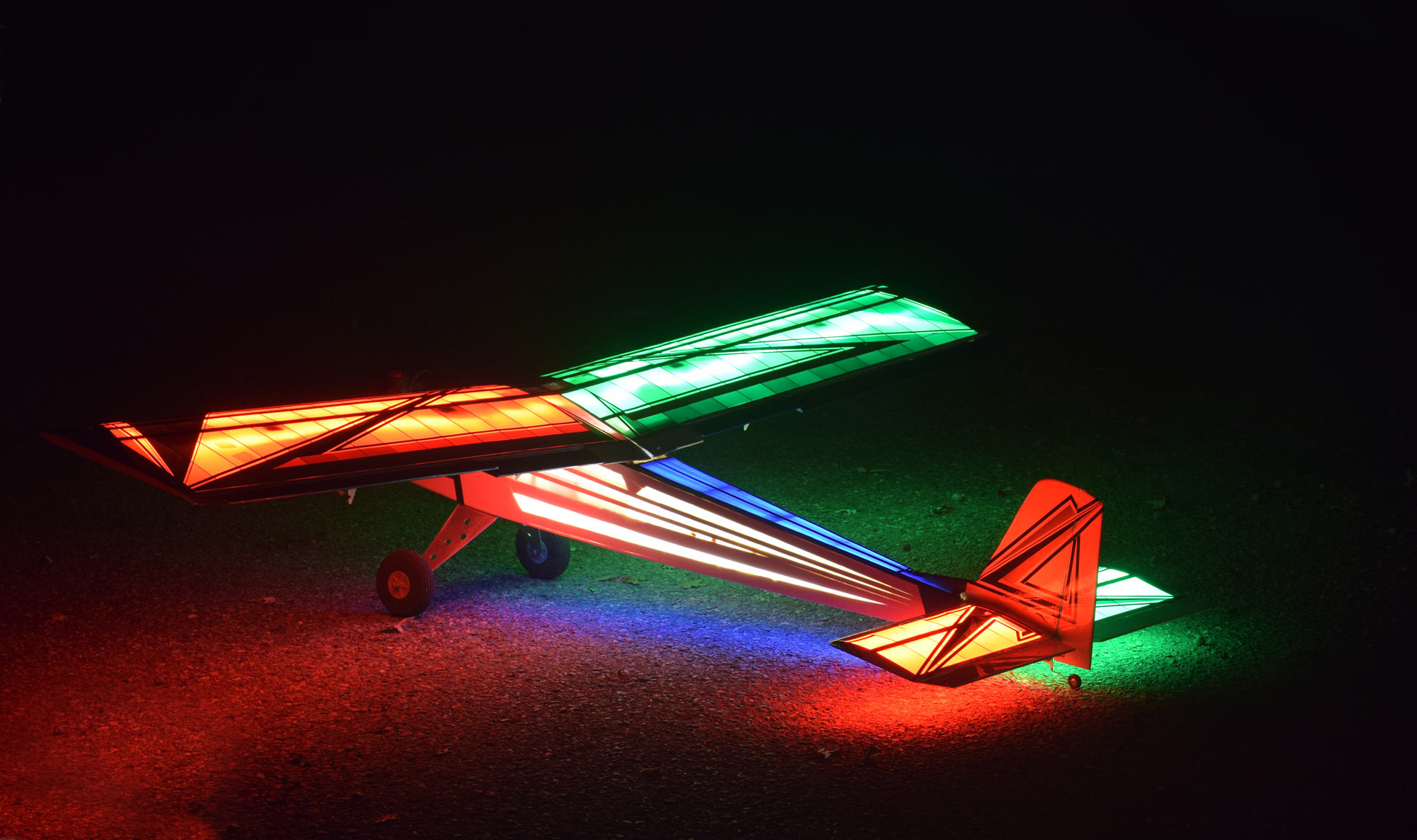
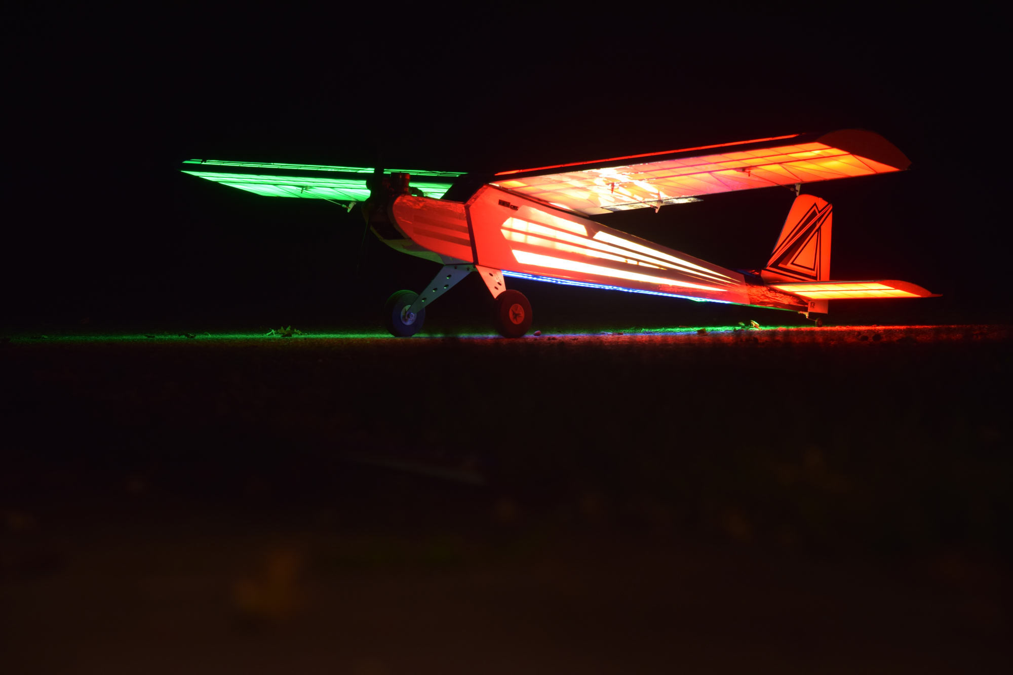
One other item I wanted to do was add some lighting to the wings and the fuse. Originally I had just added some LED strip lights to the main wing during my first round of repairs, but after my initial testing I decided I wanted to light the entire plane!
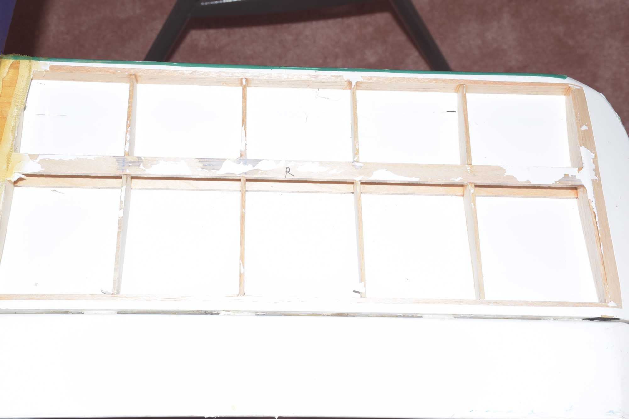
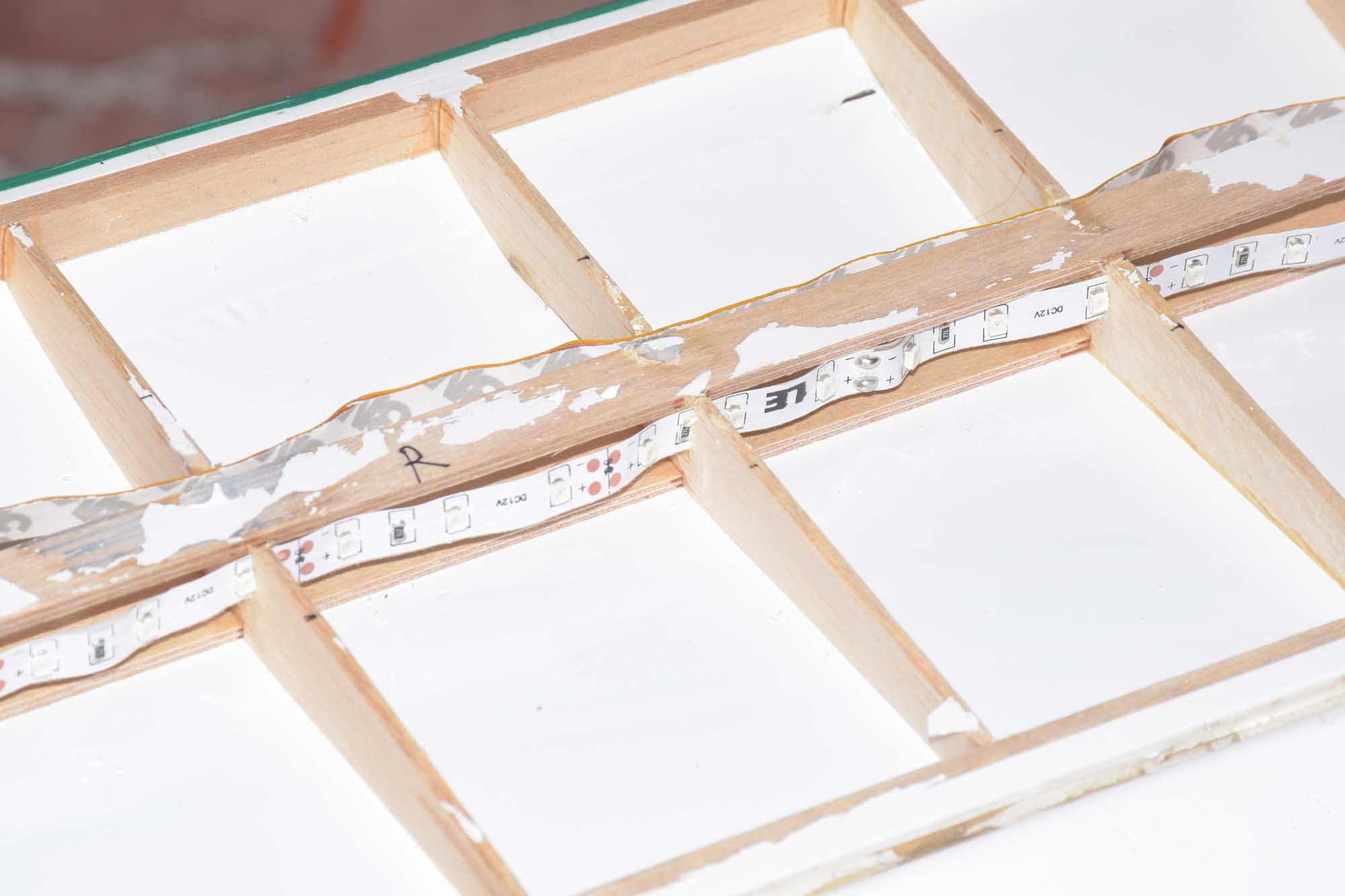
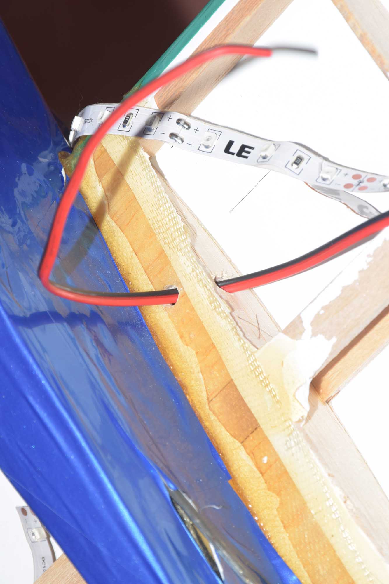
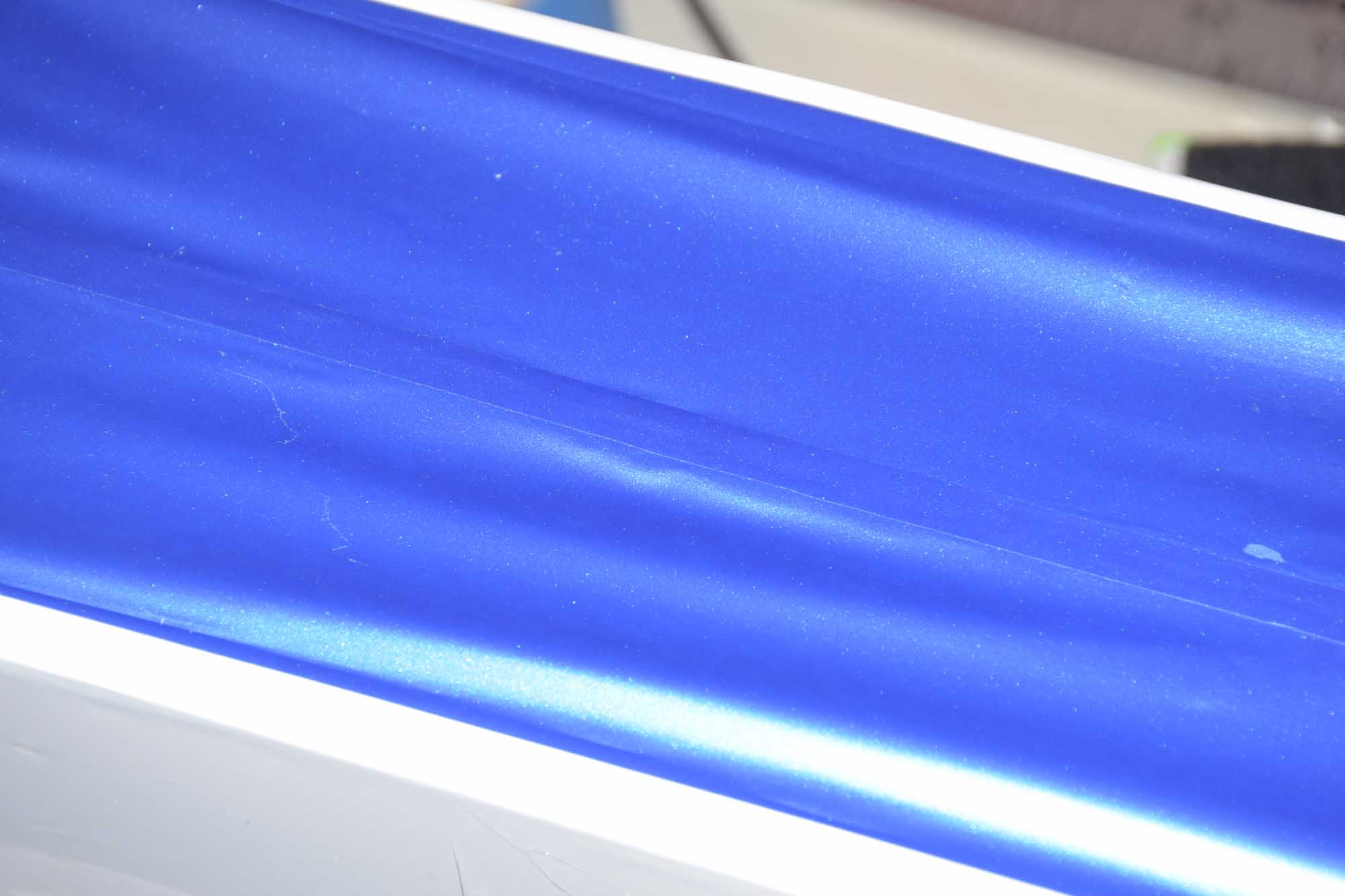
When I was recovering the wings with Ultracote, I drilled wholes in the ring ribs so I could run the LED strips through the wing. I ran a set in the front of the spare and also at the rear of the spar so I could light the entire wing. One thing I wanted to keep in mind when positioning the LED strips in the wing was to try to position the LED’s in such a way that the wing was “indirectly” lit – taking advantage of the internal reflection of the white Ultracote. This makes the lighting appear evenly distributed throughout the entire wing giving it a more natural “glow” effect.
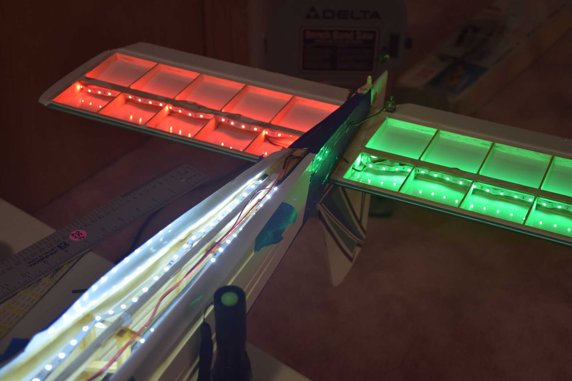
The main colors I used for the wing and the horizontal stabilizer, were red and green – with the green LED’s on the right and red on the left. I used neutral white for the fuselage interior. I placed the fuselage LED strips on the bottom so they could shine up – again taking advantage of indirect lighting. Using this technique where possible really makes it glow and the light looks very even!
-
- Removed the old covering for access to the bottom
-
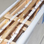
- positioned in ribs
-
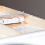
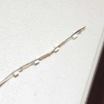
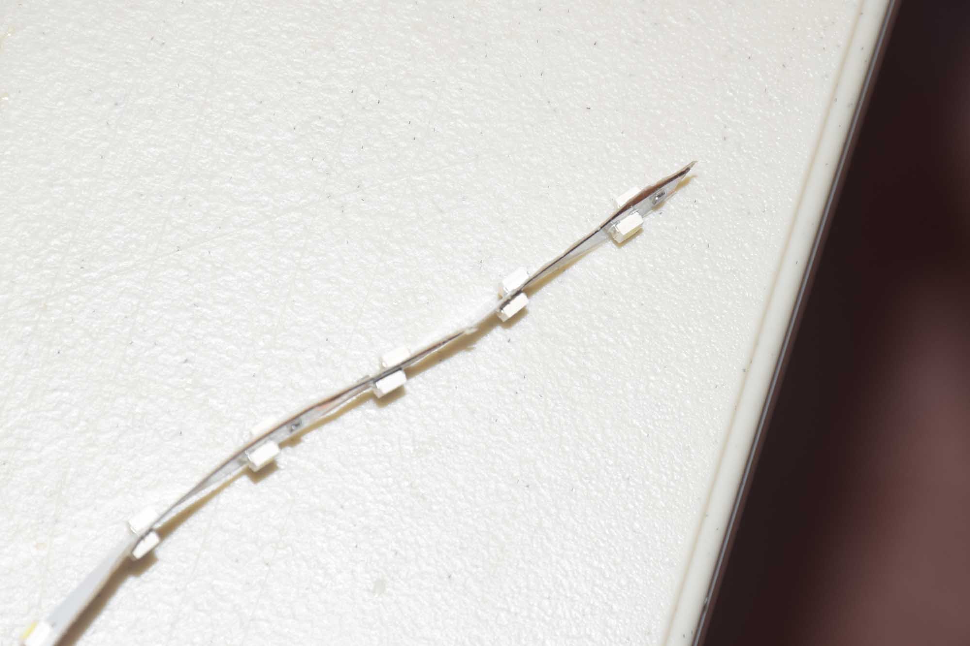
- LED strip, shining outward
-
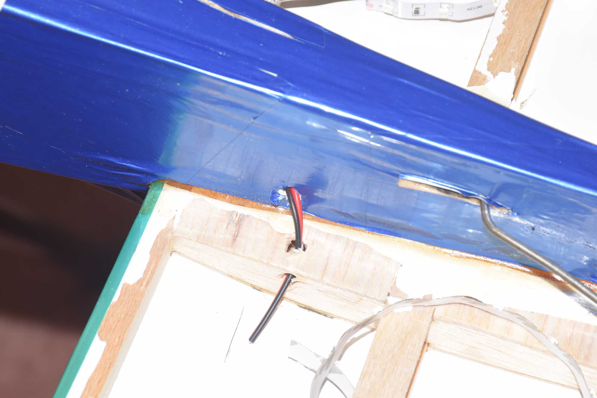
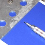
- drilled small holes for wires
-
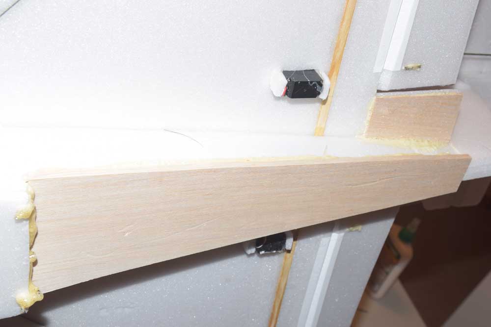
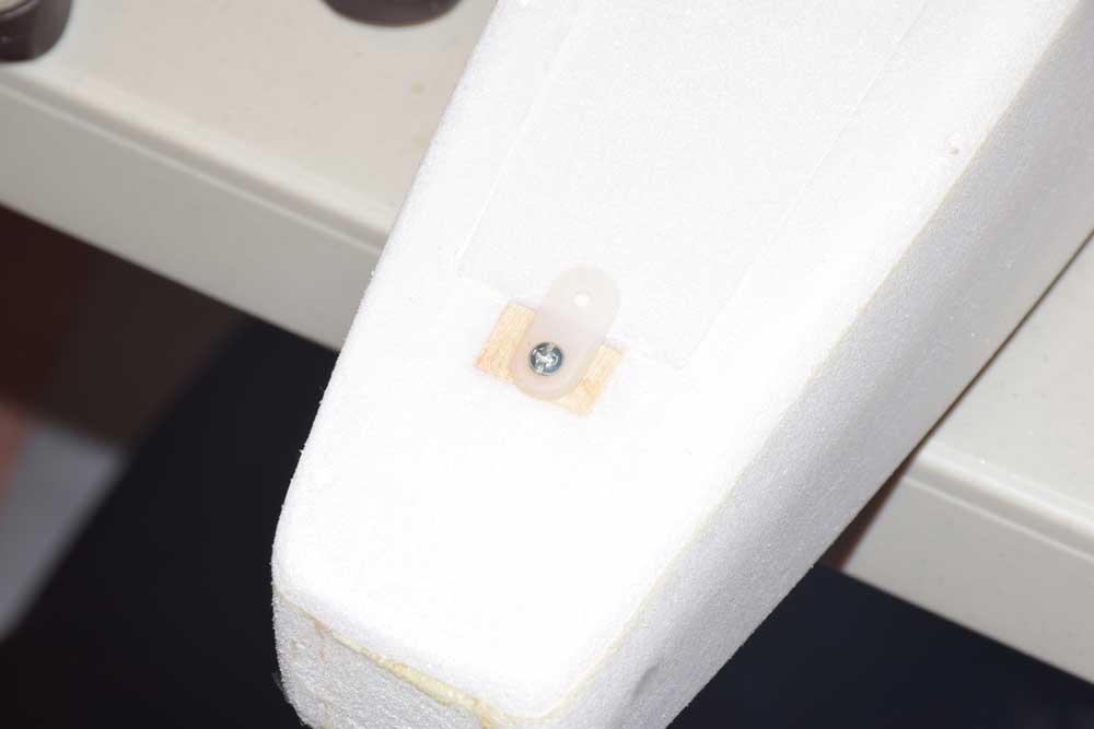
- drilled small hole in fuse to run wires inside of the fuse
-
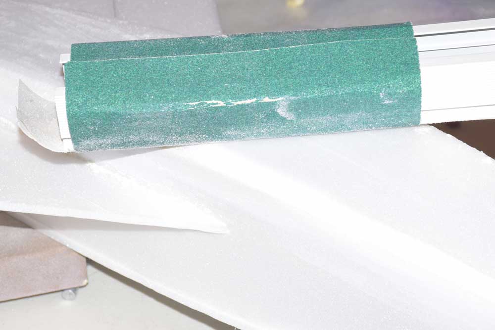
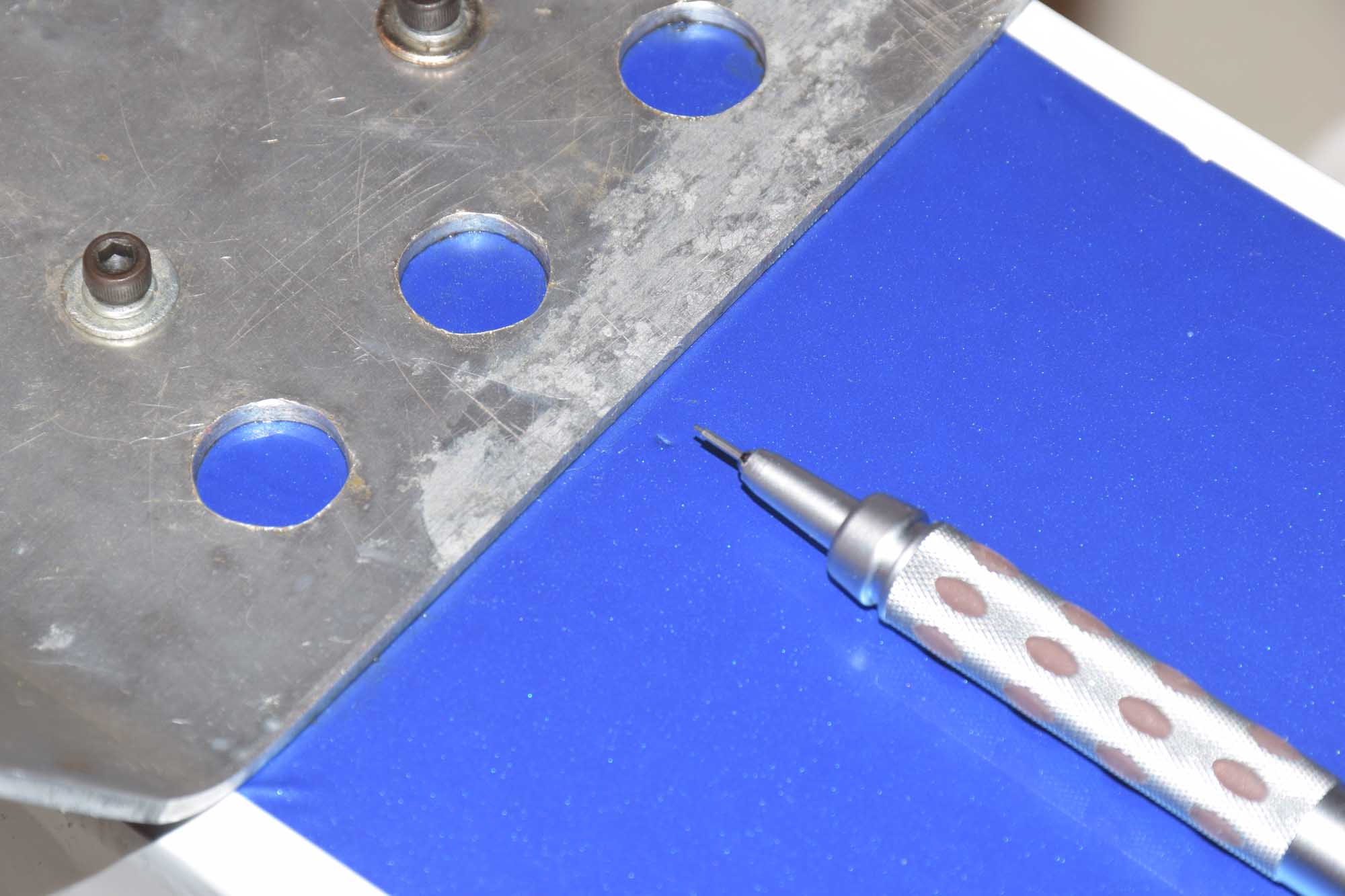
- Measuring the amount of covering I will need
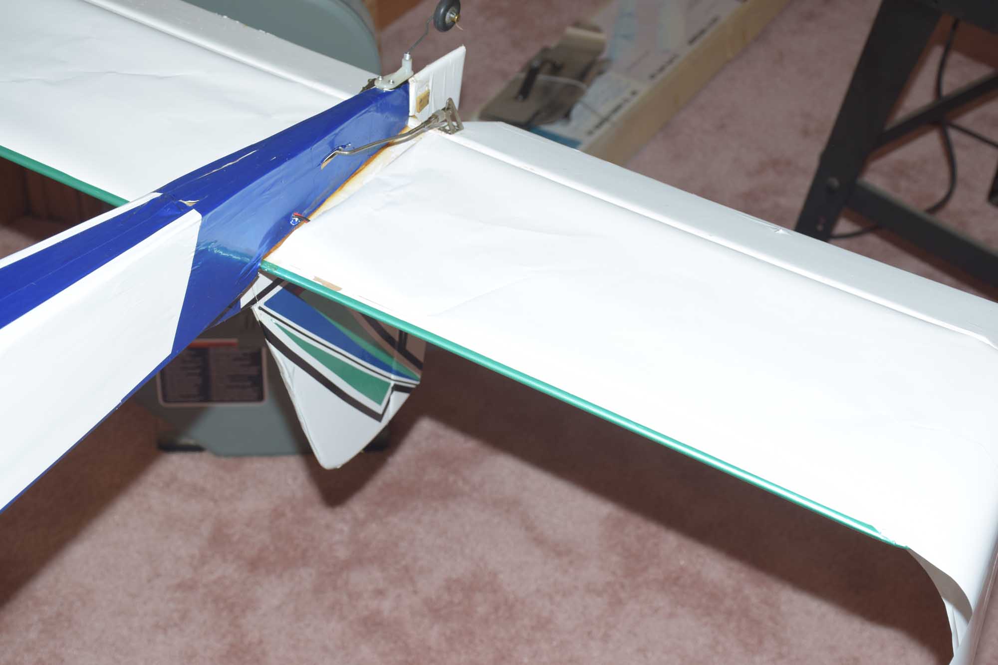
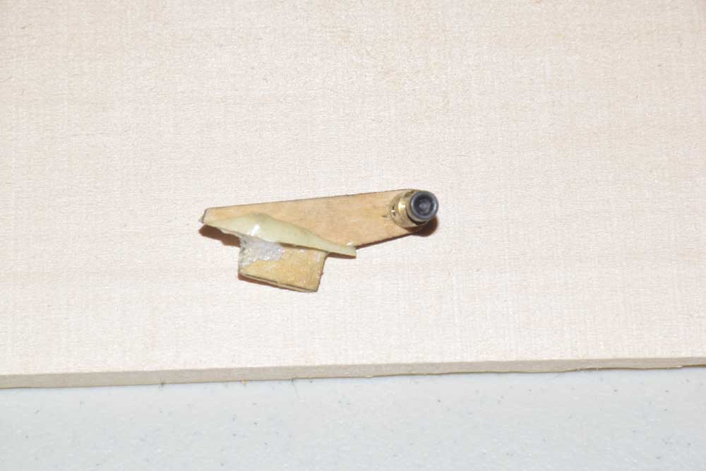
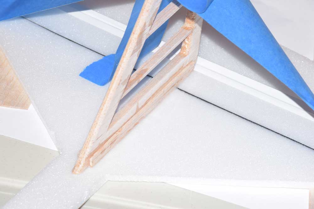
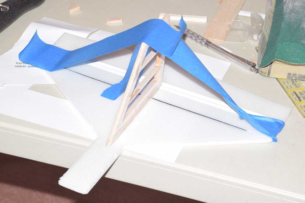
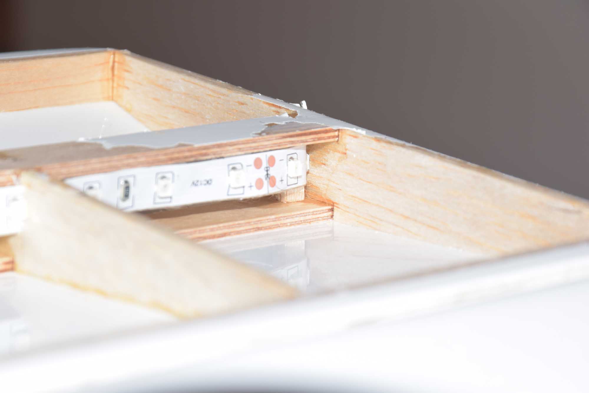
When it came time to install the LED strips into the horizontal stabilizer, I developed a new technique for placing the lights; perhaps one I wished I would have thought of instead of drilling holes in the ring ribs! Sometimes you “learn as you go”! For the horizontal stabilizer, I cut small slits in the rib and slid the LED strip in place as close as I could to the spar location. Once I was satisfied with the positioning, I added some thin CA to the small gap to restore the integrity of the ribs in the stab (the Telemaster uses an air foiled design for the horizontal stabilizer). Again, I ran a strip in front of the main spar and also at the rear – both strips shining outward from the center. This made for very even light distribution!
-
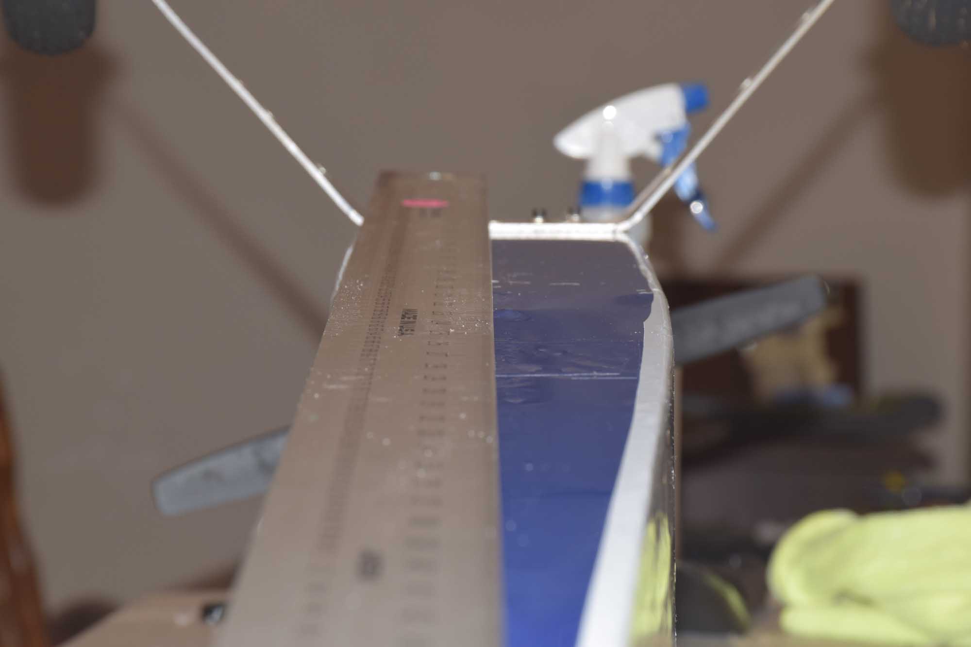
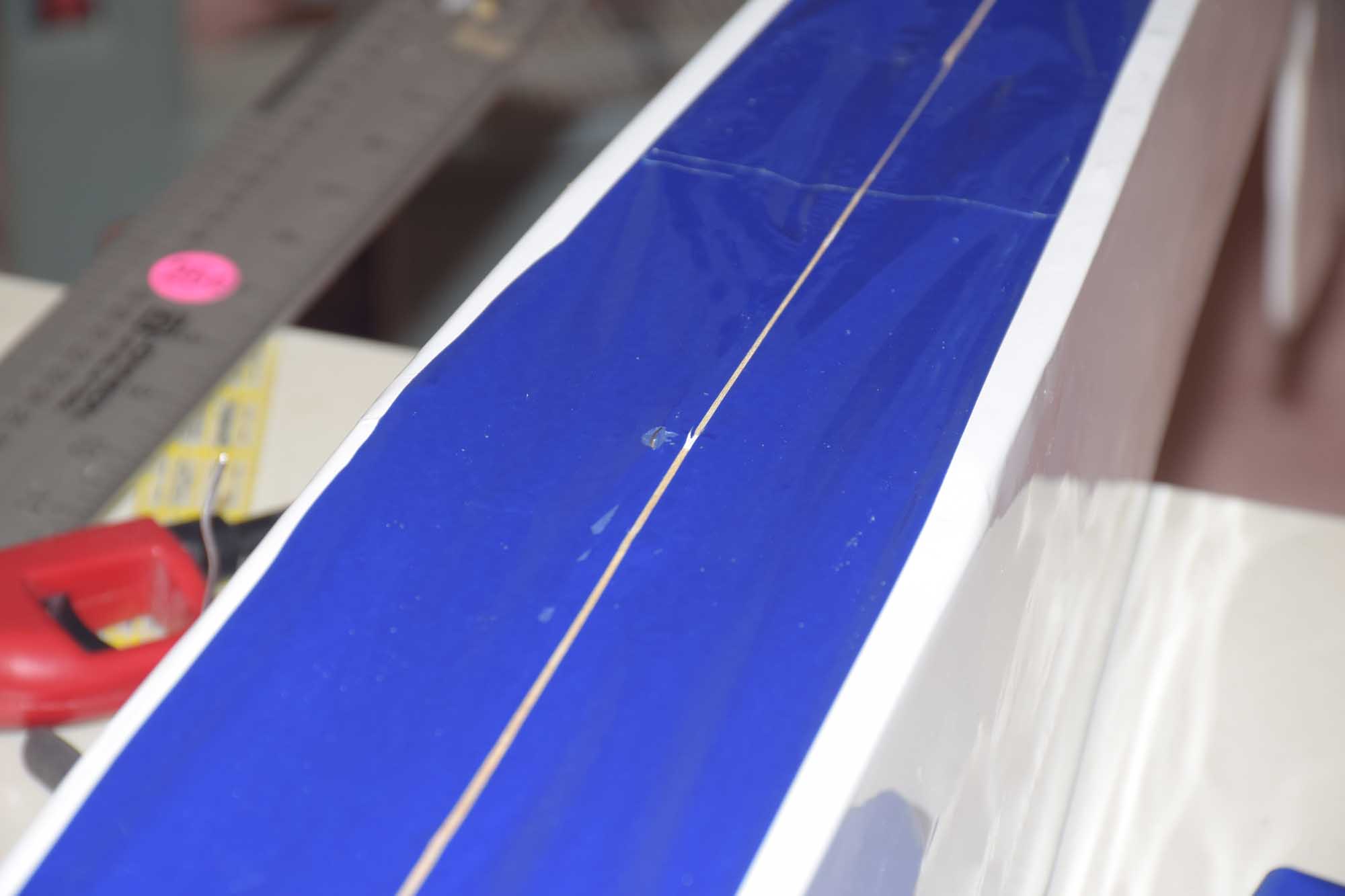
- Marking center of fuse line
-
- Use a straight edge to make a nice clean cut in the covering
-
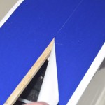
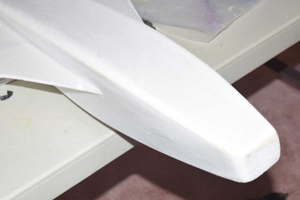
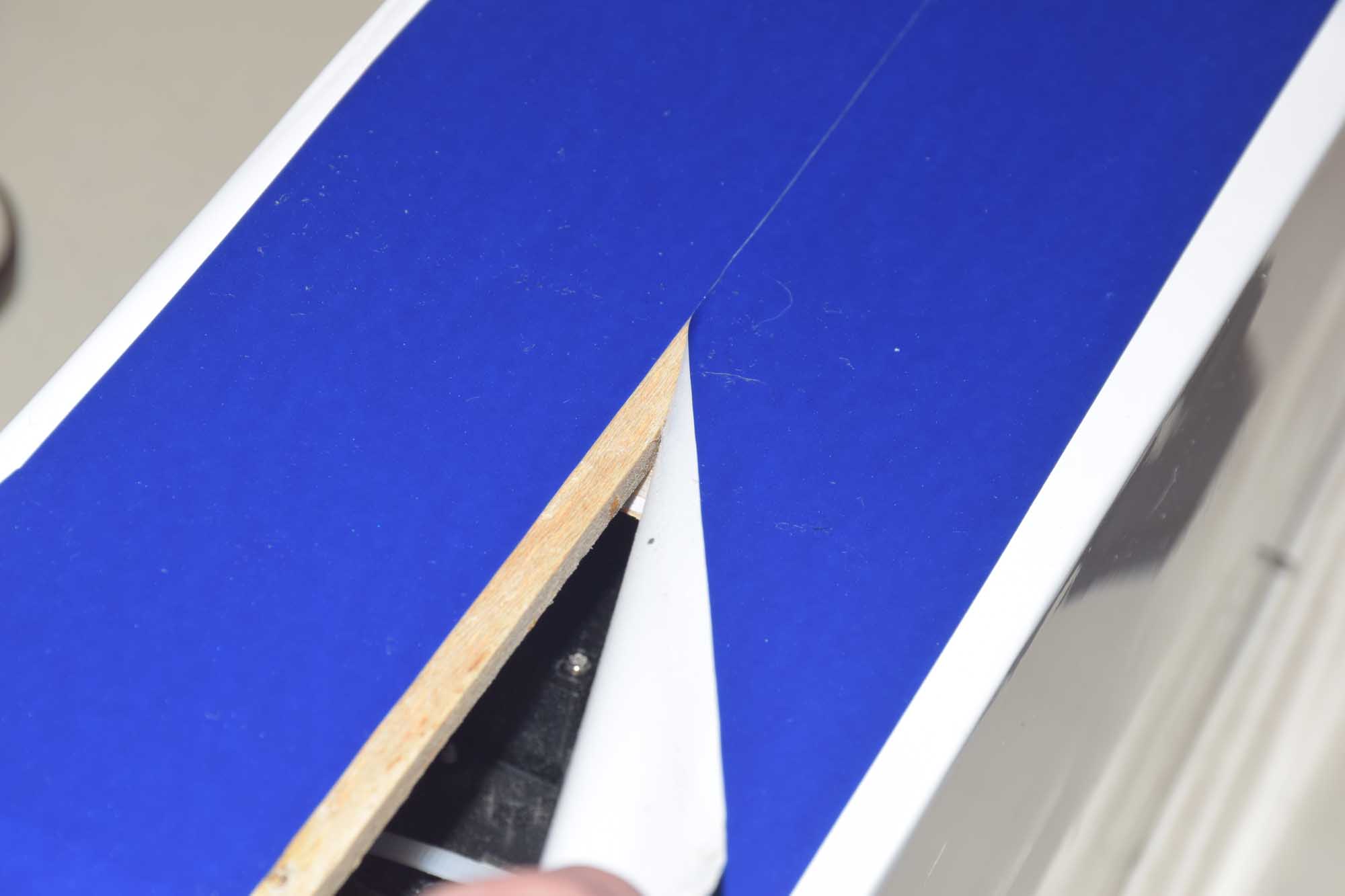
- gently begin to peal it back to expose the fuselage.
-
- Use tape to hold covering out of the way
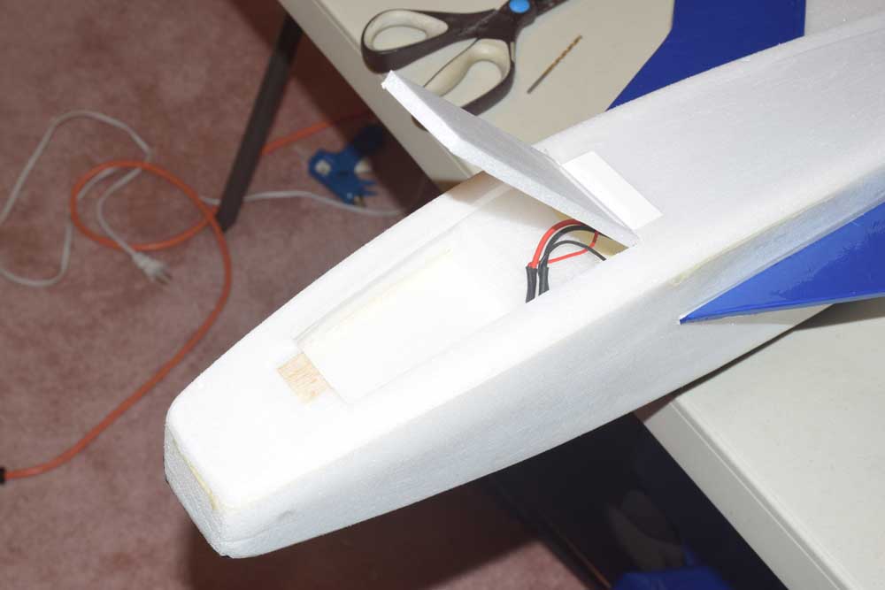
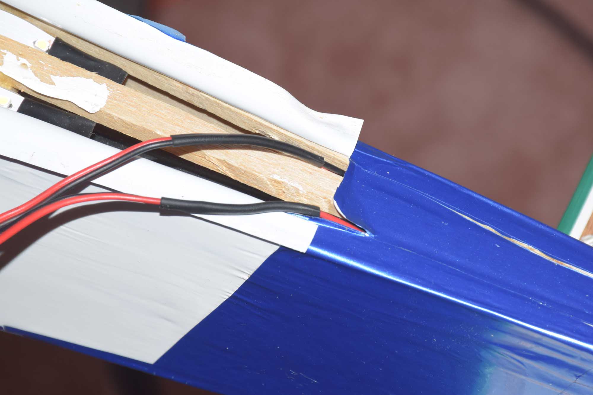
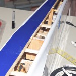
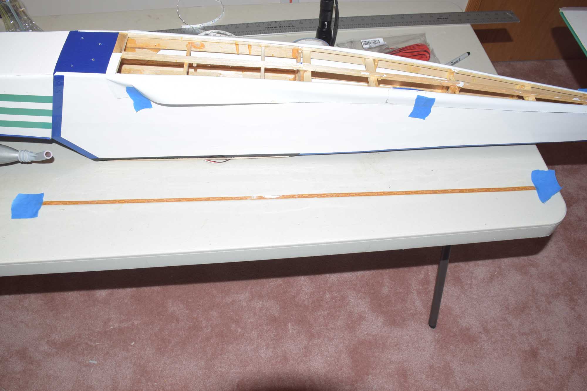
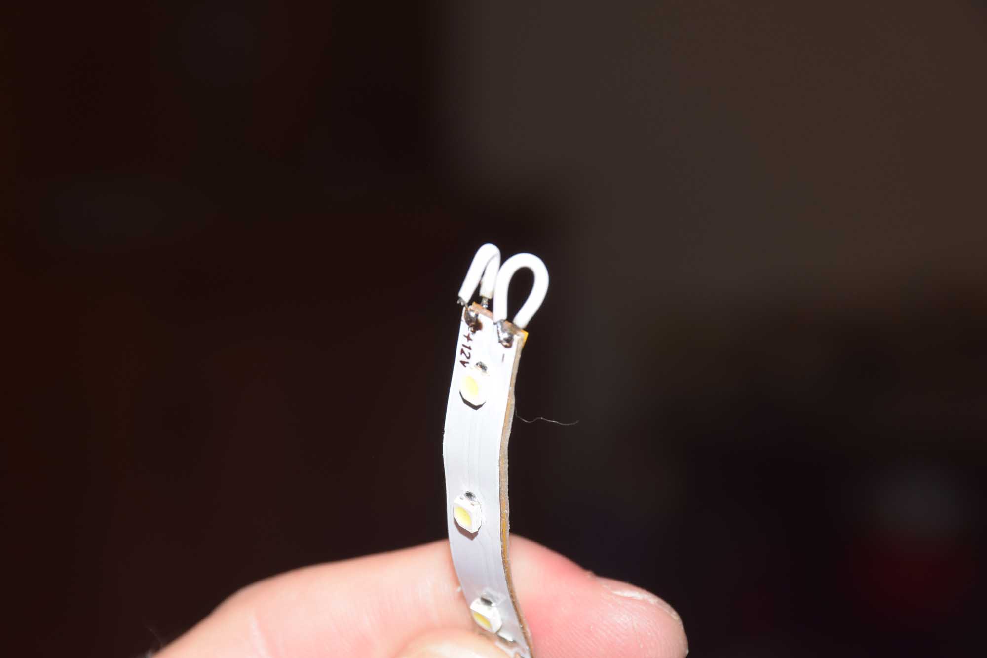
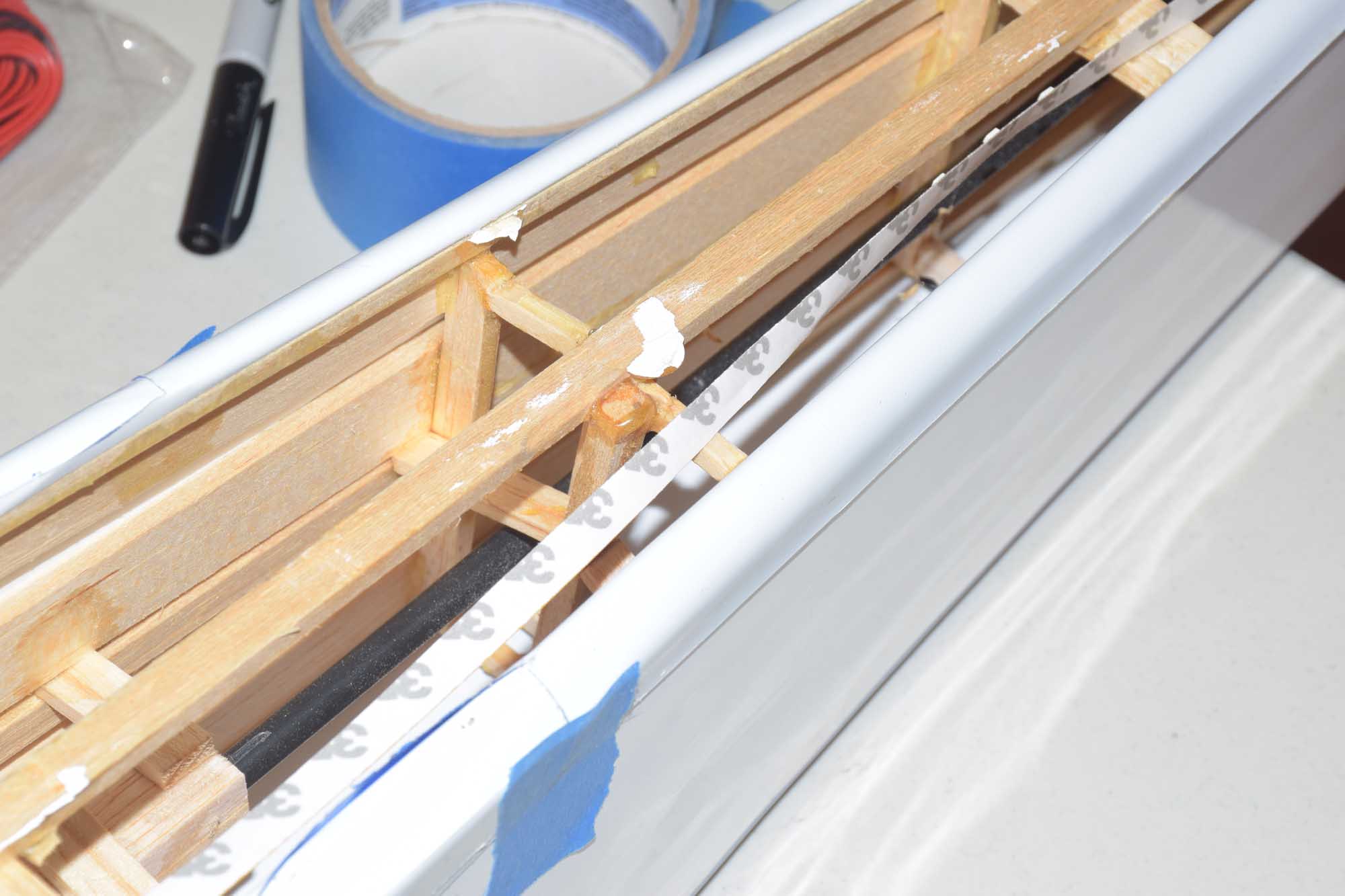
Installing the light in the fuselage, I decided the easiest method was to cut the covering down the very center using a straight edge so I could access the entire bottom of the fuselage. Of course hindsight would dictate to install the lights before I covered it the first time! For the LED strips in the fuselage, I stuck two strips of lights back to back (in this case I did want one set to show down and one set to shine upward into the inside of the fuselage). I ran two double strips on each side of the center line of the fuselage. I wired the back-to-back pieces together using jumpers I had made from some scrap servo lead wire.
-
- sticky side up
-
- position one strip sticky side up
-
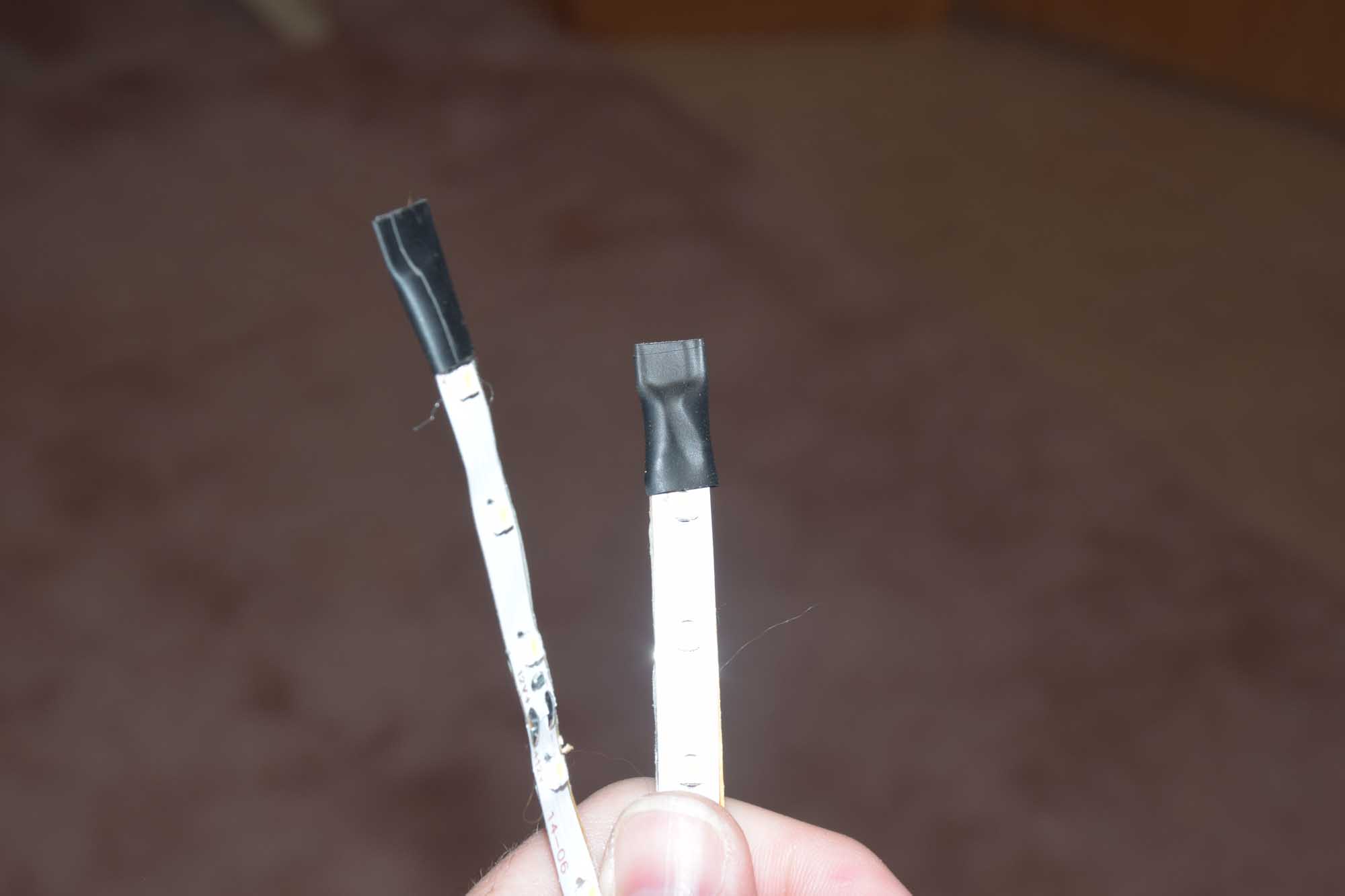
- LED’s stuck back to back
-
- test fitting inside of the fuselage

-
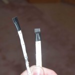
- cover exposed ends.
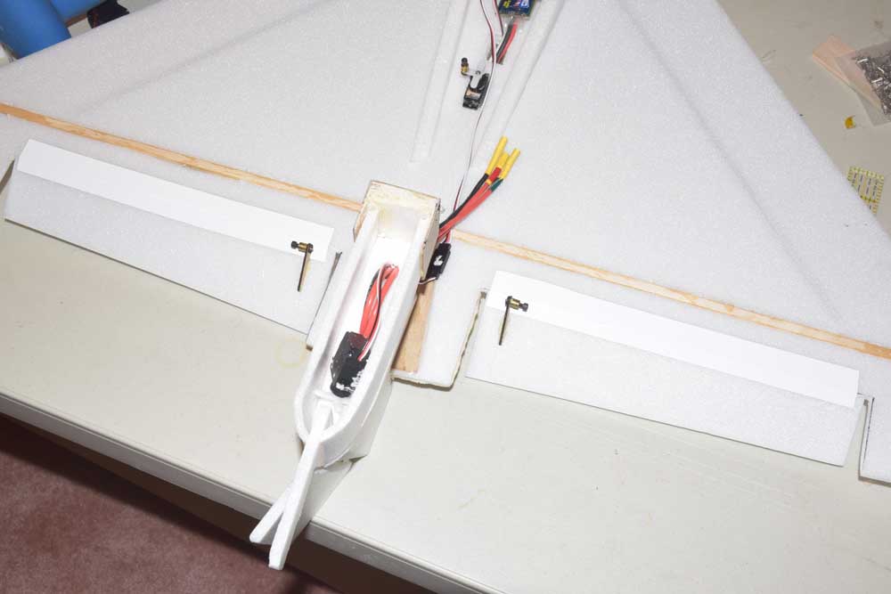
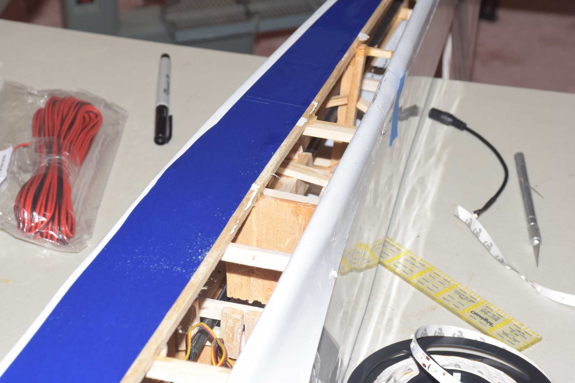
Once I was satisfied with the placements of the lights, I secured the LED strips and wire leads with a hot glue gun. Hot glue works very well for this sort of thing!
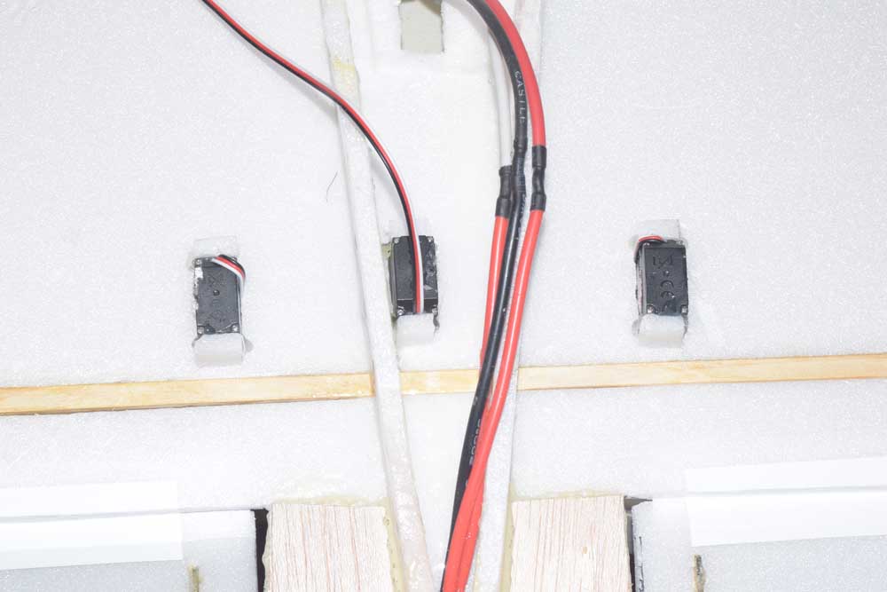
I wanted to be able to control the LED lights from my transmitter. I decided to use the Turnigy Receiver Controlled Switch to do that. This switch simply gets wired into the positive lead of your battery, and the other end connects to an open channel in your receiver. Since this plane is a glow powered plane, I’m using two separate batteries, a normal NiMH 5 cell – 6.0 volt pack for the receiver and servos, and a 3S lithium polymer battery for the LED strips. One thing to note, is that for this circuit to work properly, the ground (black wires) of both batteries need to be connected together! Without doing this the switch will not operate! I’ve included a wiring diagram of the configuration for this type of setup. Mode II is the diagram you should follow when using two separate batteries.

https://www.hobbyking.com/hobbycity/store/catalog/e-switch.jpg
Here’s a YouTube video that explains the switch modes in more detail:
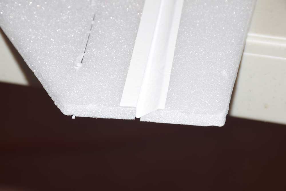
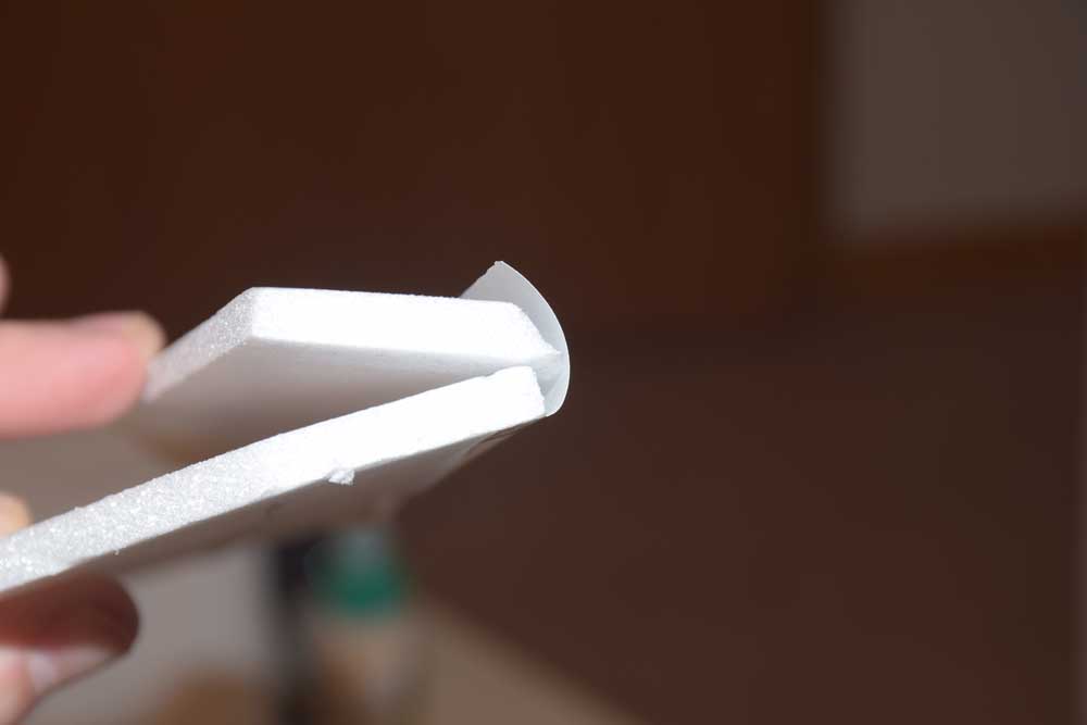
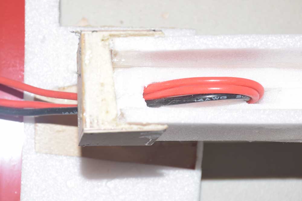
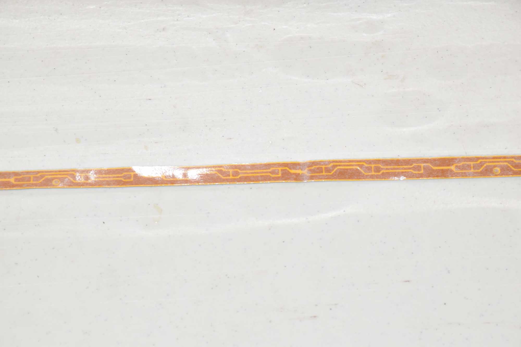
After all the lighting was installed it was just a matter of resealing the bottom covering and a very thin strip was needed to cover the bottom seem.
-
- Iron down the covering
-
- seal center seam – then re-heat with iron to shrink tight
-
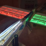
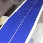
- testing circuit before covering put back in place!
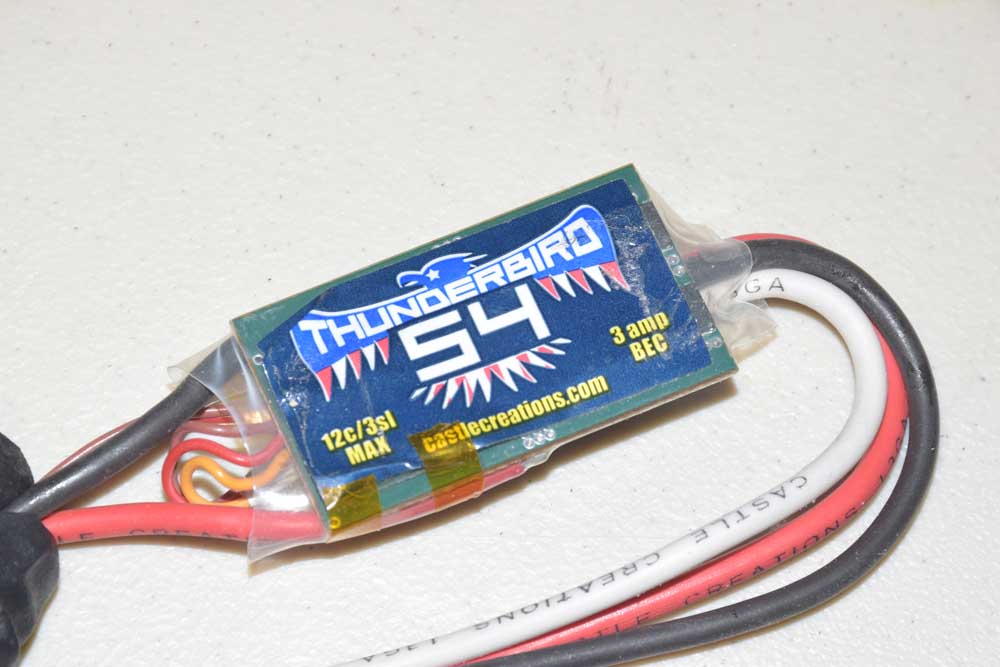
With all the LED’s in this setup, the entire system draws roughly 3-4 amps. I’m using a 3S 1300 mah lipo for this particular setup.
Good luck with your LED project!