Monthly Archives: October 2015

Sig J-3 1/4 Scale Cub Build Series – Part 3 – Stabilizer & Elevator

Part 3 – Horizontal Stabilizer and Elevator 


Building the horizontal stabilizer and elevator are pieces that can also be constructed quickly.

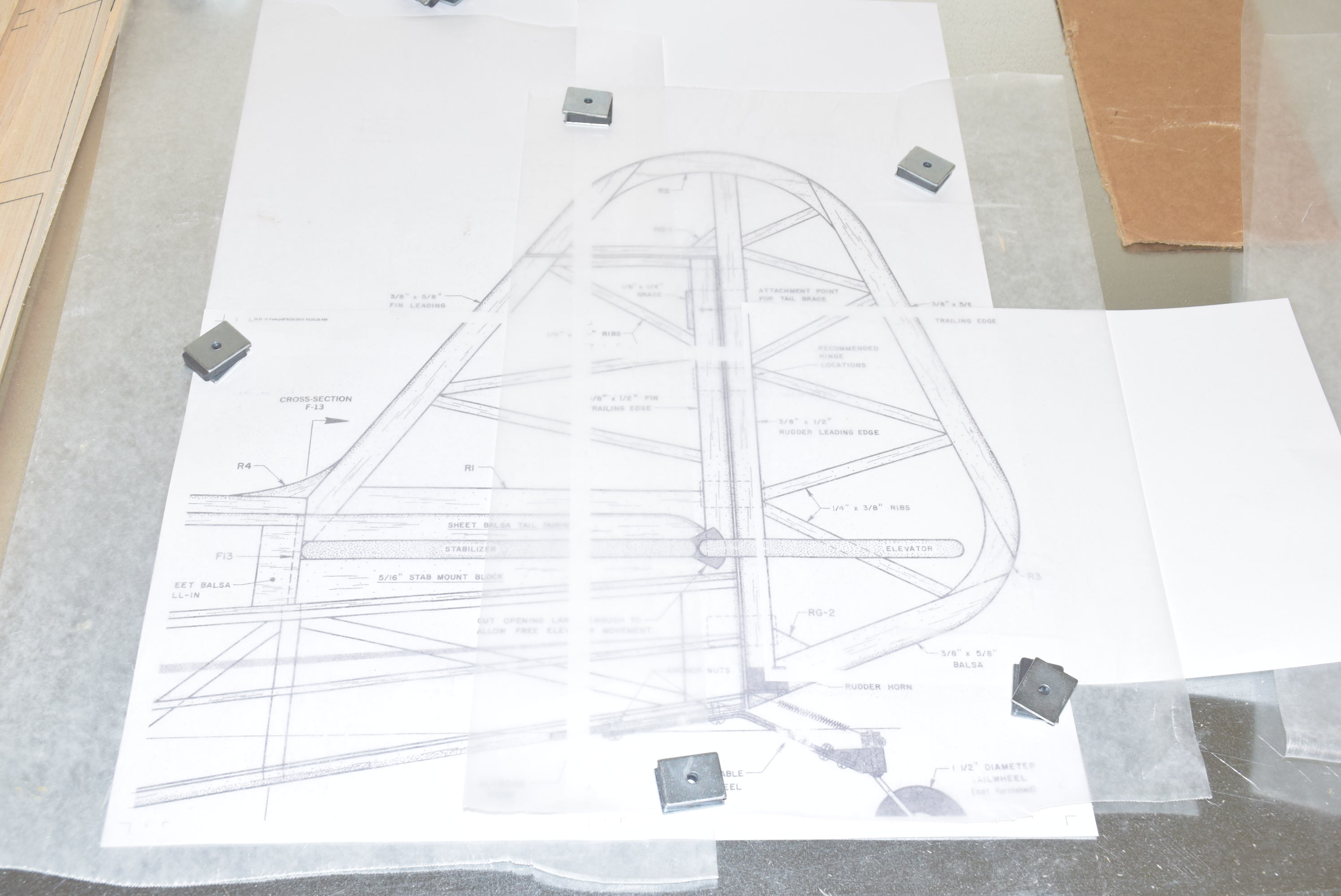
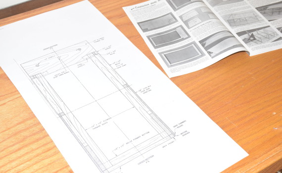
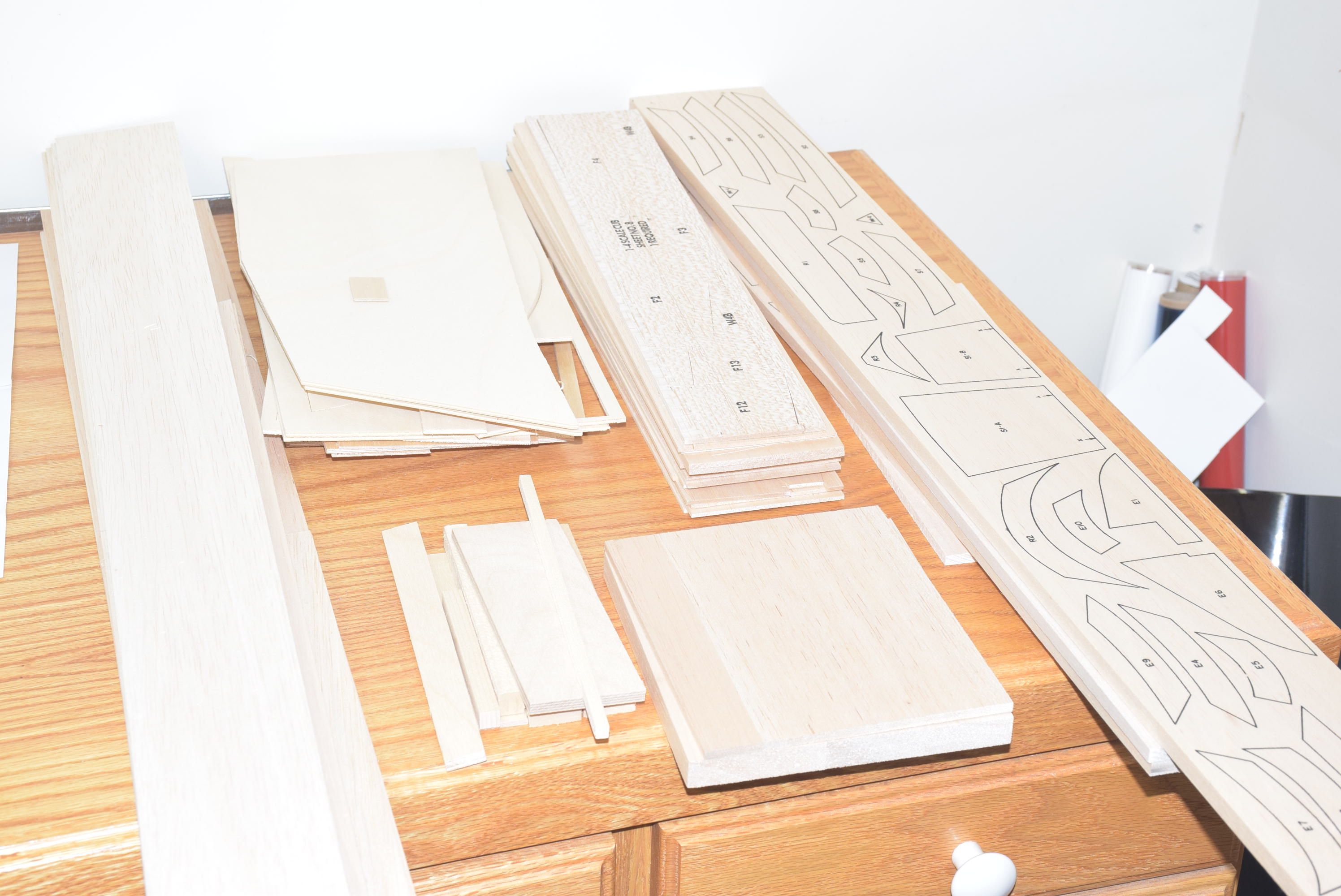
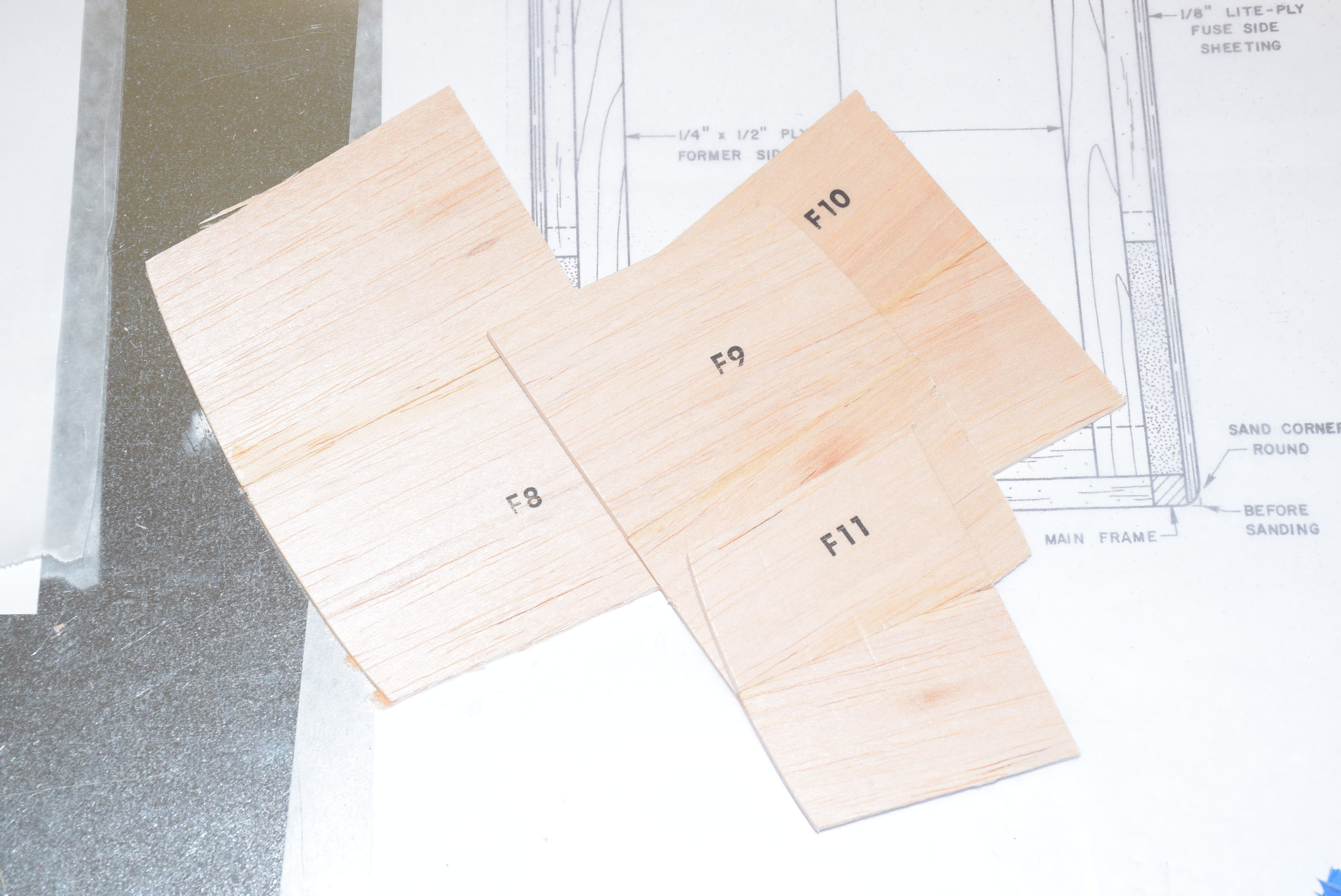
Most pieces for the horizontal stabilizer and elevator are included on printed 3/8 balsa sheets. Be sure to also set aside the included stick pieces you will need for this build and make sure they are of the proper thickness as shown on the plans.

I started by rough cutting the printed pieces on a band saw.  Since there are quite a number of pieces it best to do this while your mind is fresh.  Having to cut out all these pieces can be a little time consuming and start to  feel repetitive.
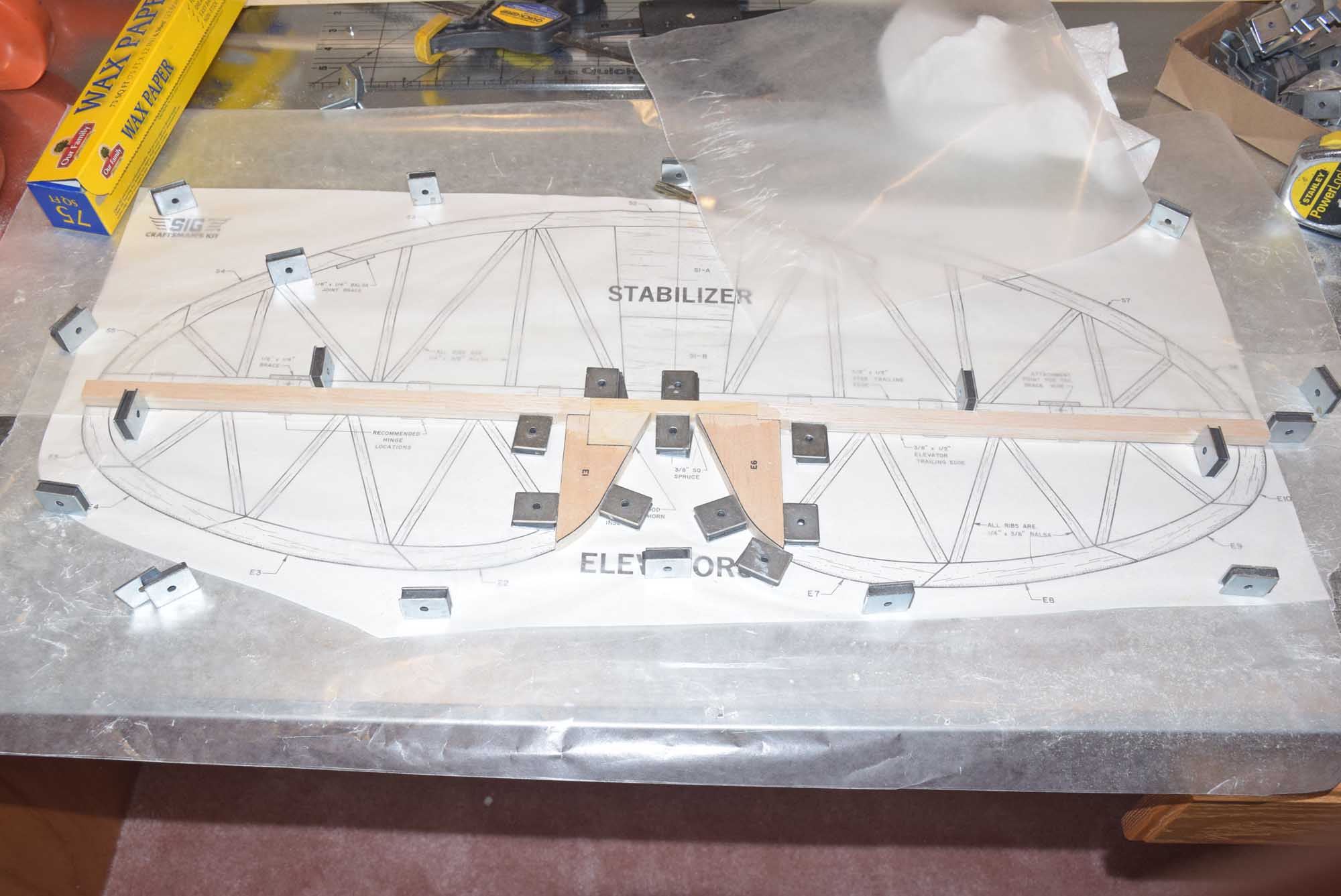
 

Elevator
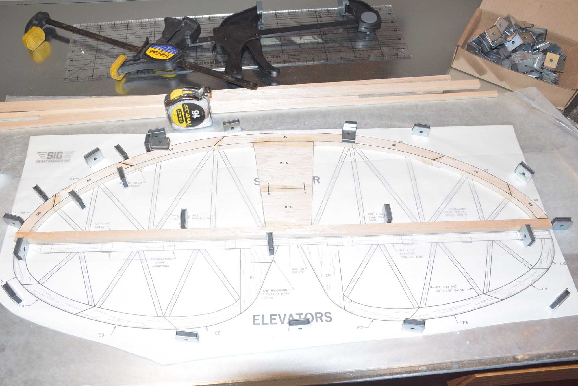
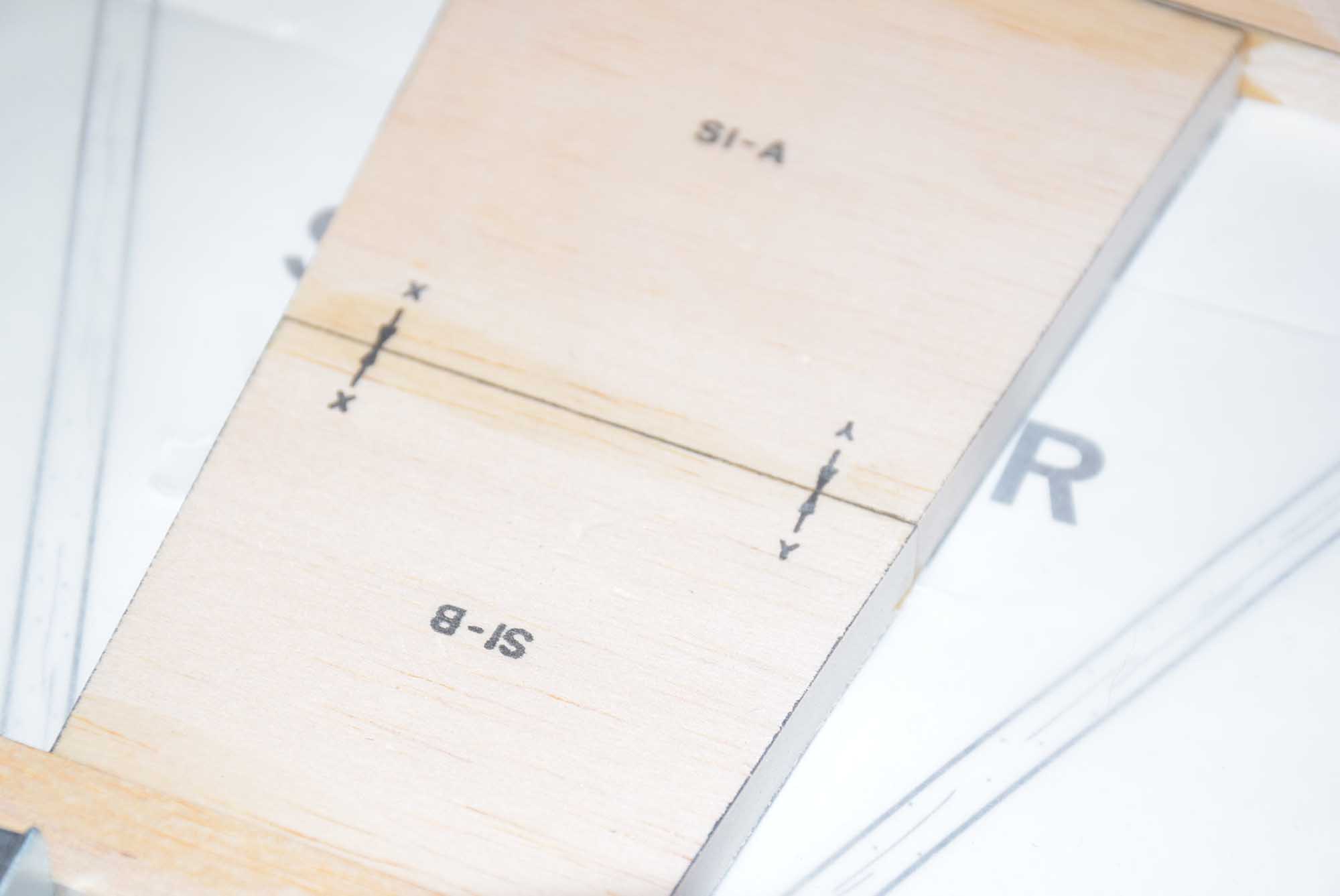
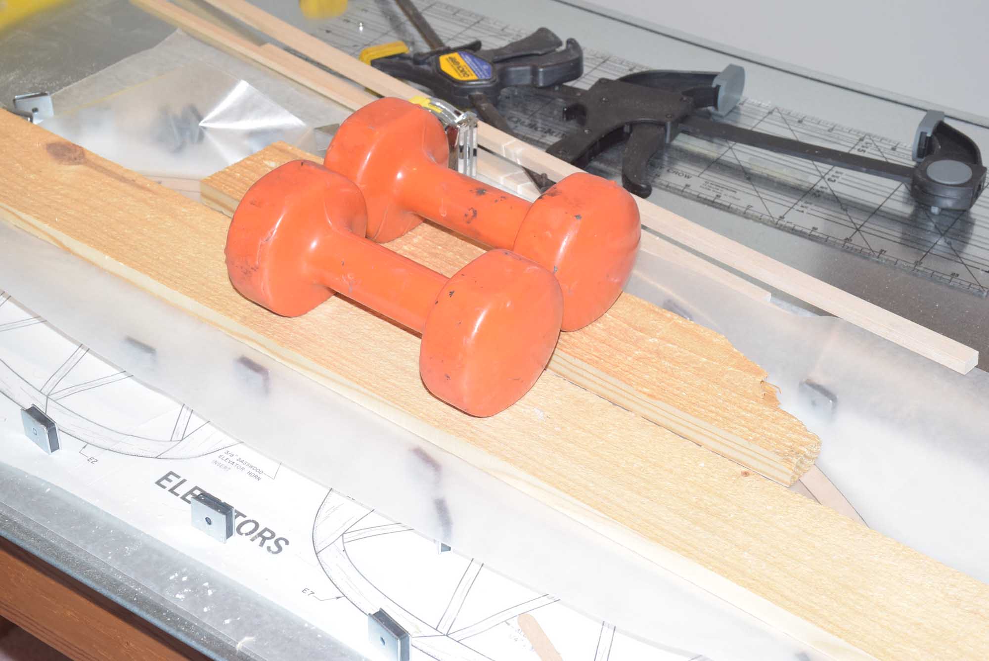
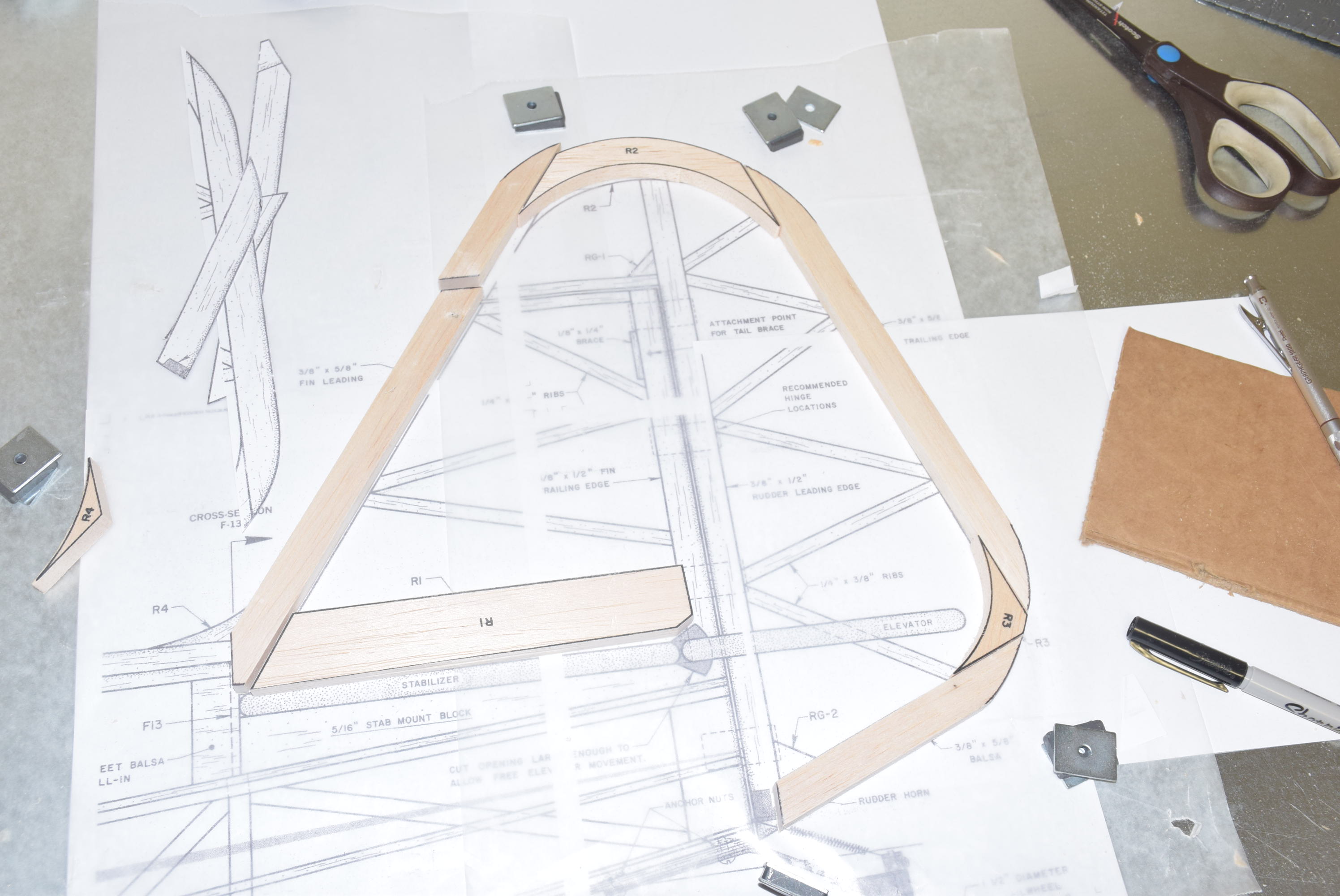
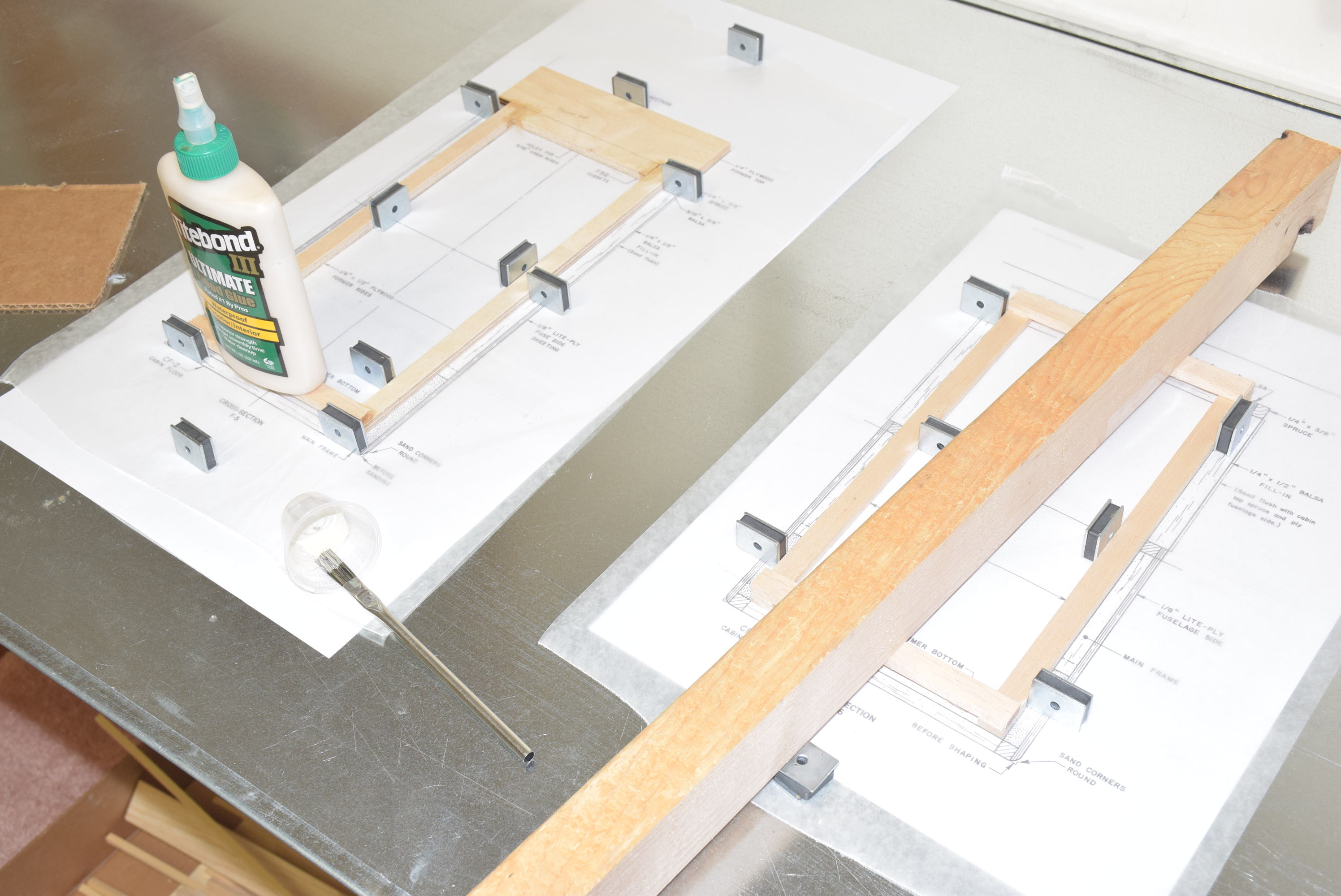
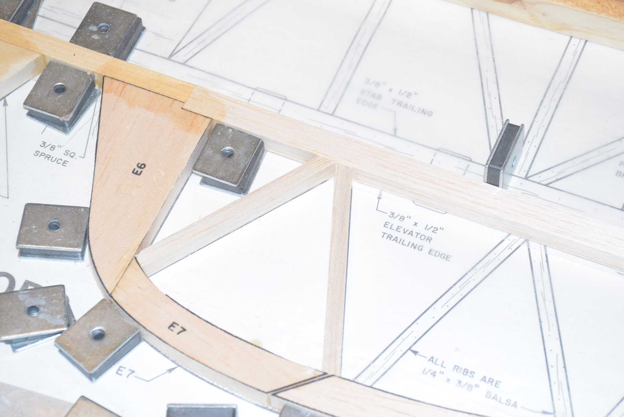
Once all the parts were cut out, I set them aside and started with placing the 3/8 x 1/2 inch balsa sticks in place over the plans.  There is also a 3/8 spruce center piece.  I placed the spruce piece over the plans as accurately as possible and then cut the two 3/8 balsa outside sticks just a hair longer than needed.  Use a straight edge to make sure the sticks are as straight as possible along the hinge line.  This will help reduce any hinge gaps later during assembly.  I placed the E6 and E1 parts in place over the plans along with the spruce elevator horn block and glued this sub-assembly.

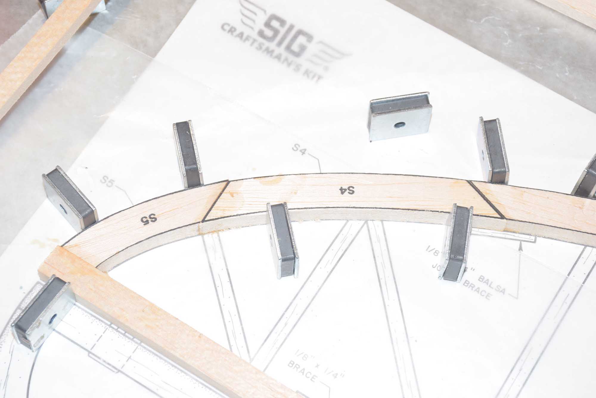
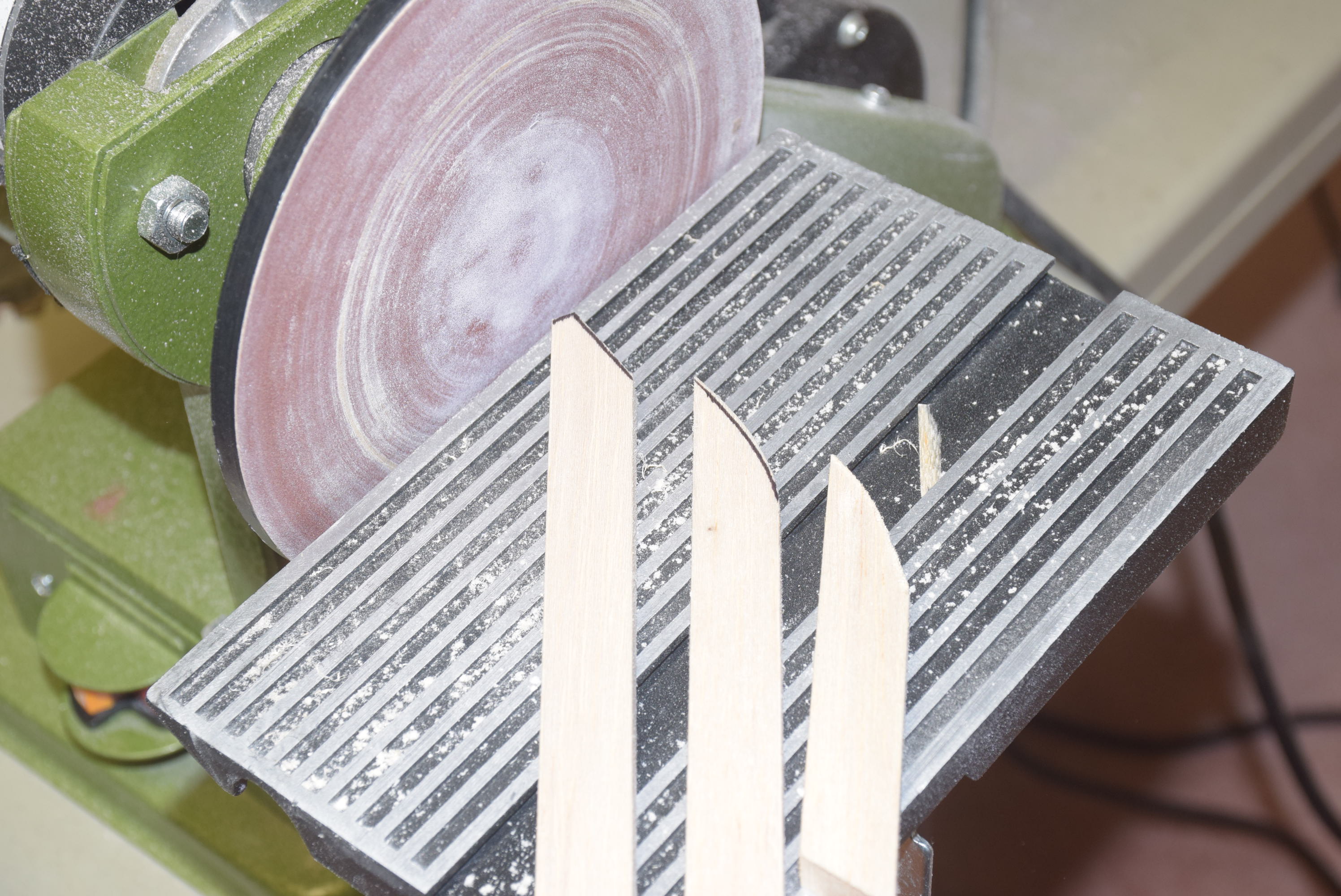
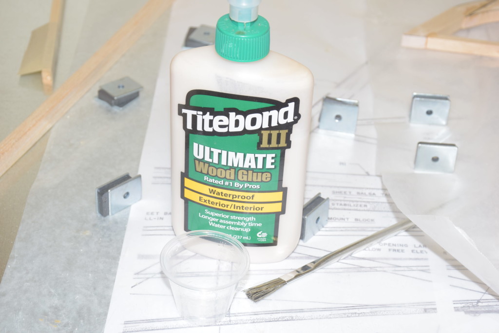
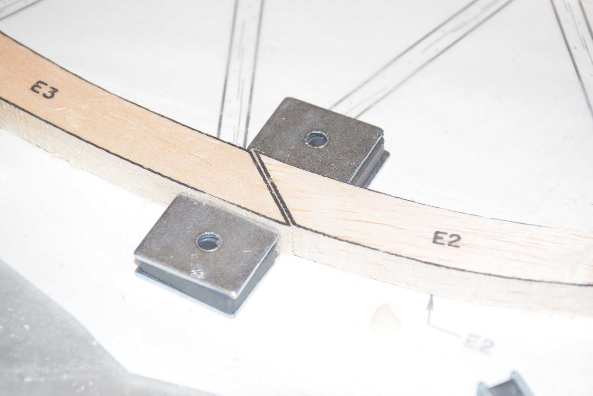
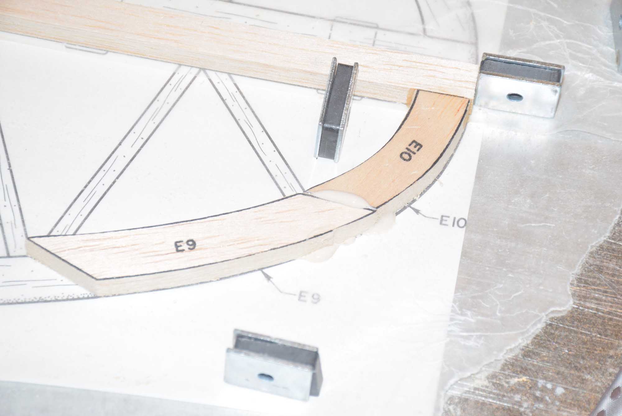
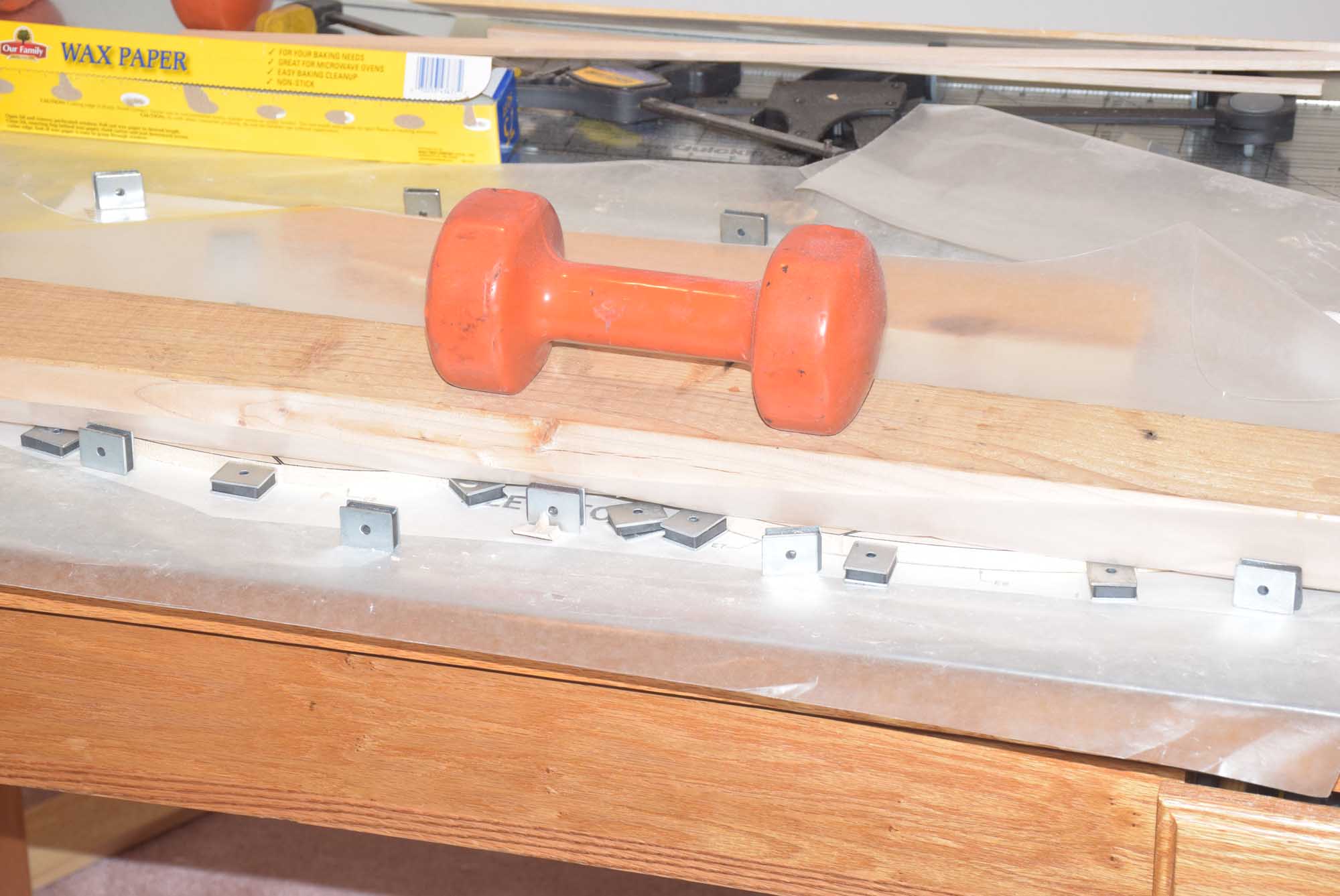
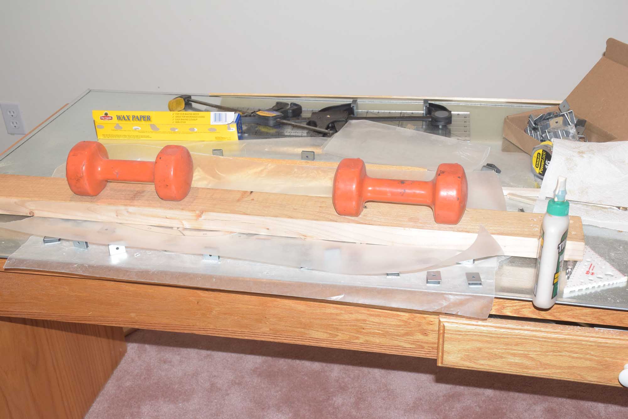
Next, I began to glue up the rest of the printed elevator parts.  I took time here to make sure each piece had a very solid and accurate glue joint – no gaps.  Use a disc sander to shape the edges of the parts accurately.  I glued in the parts one at a time and cleaned up any excess glue that would run out from the joint.  I used magnets here to hold the joints in their proper position as the glue set up.  This was somewhat of a slow process as I used a wood glue and would let each part setup fully (about 30 mins with the type of glue I was using) before going on to the next.    Using wood glue here over CA will make the joint very strong and still allow a little flex.  Once all the parts were in place I placed some boards with weights on top of the pieces and allowed it to dry over night.
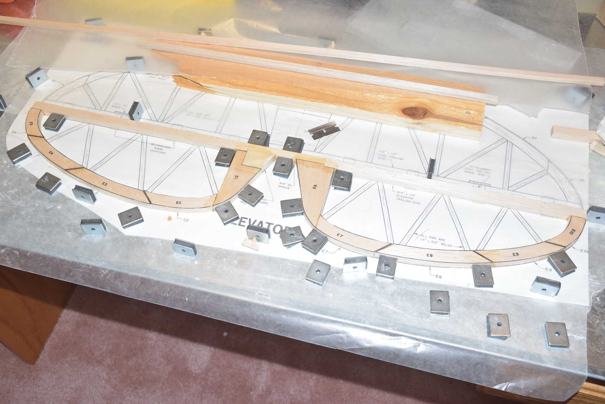
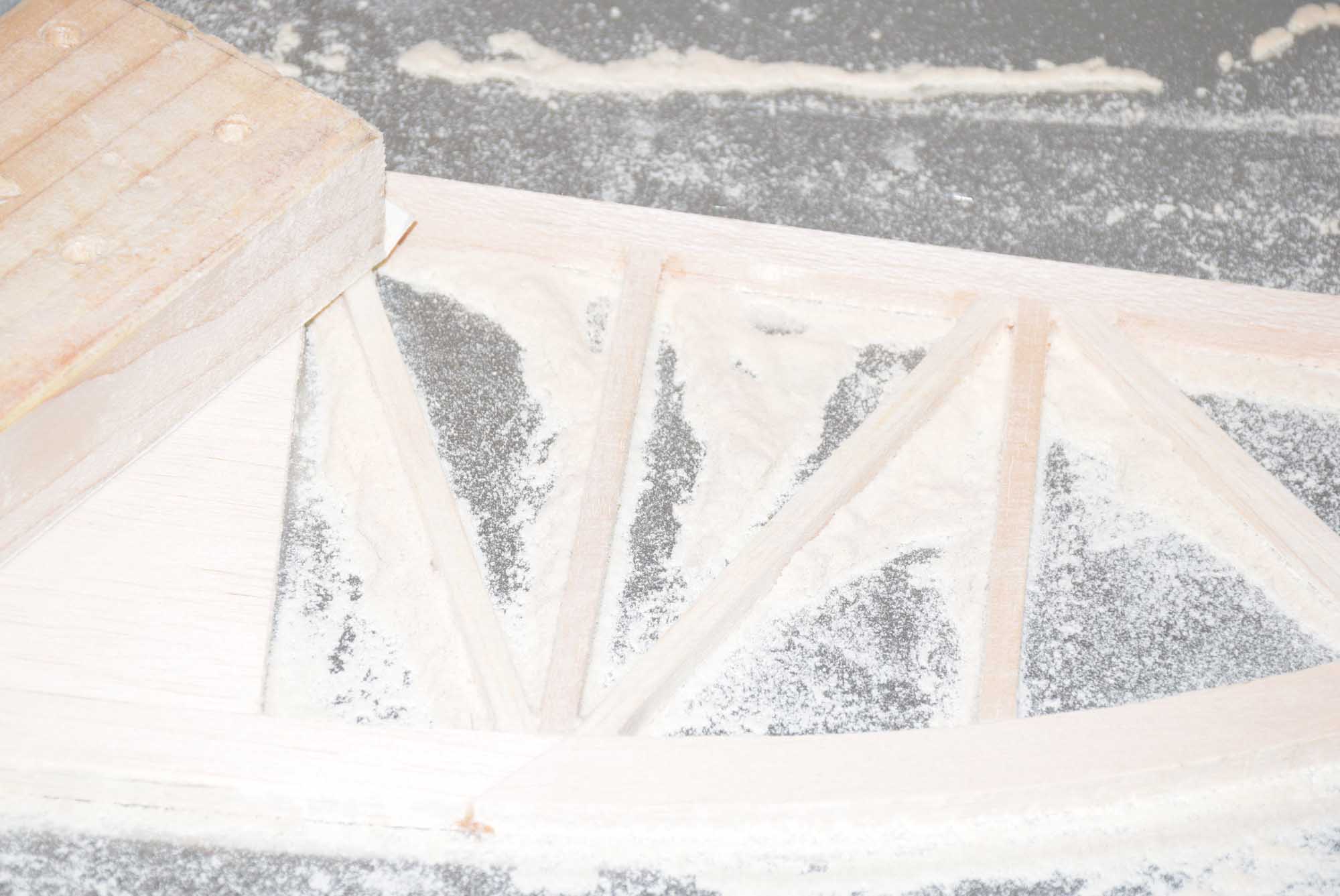
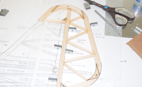
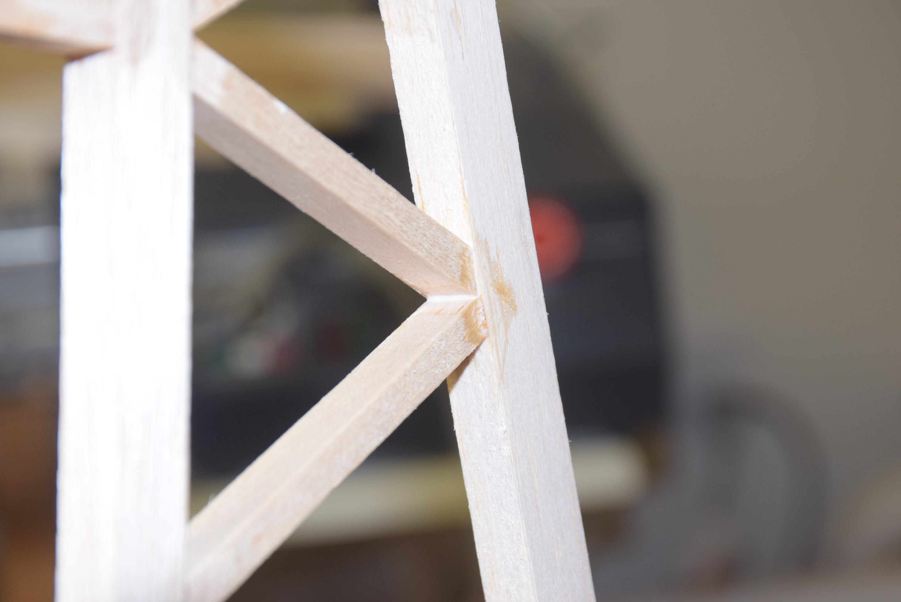
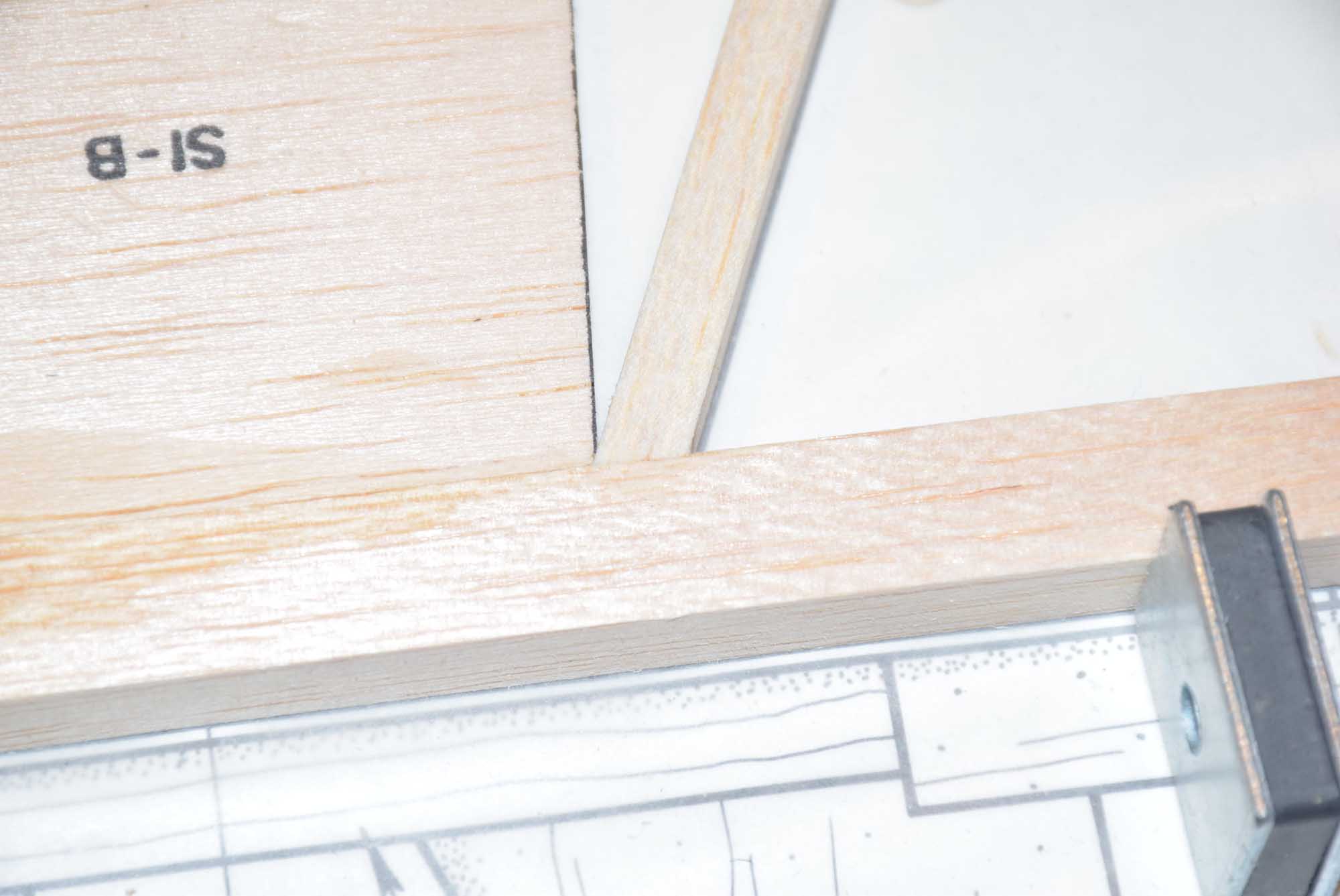
Elevator Bracing
With the main elevator parts fully dry I was now ready to work on the internal bracing.  This was done with 1/4 x 3/8 balsa sticks.  Using a tip from airfield models allowed me to get very accurate and precise joints! See the tip here: Cutting accurate truss style balsa joints

DSC_7211

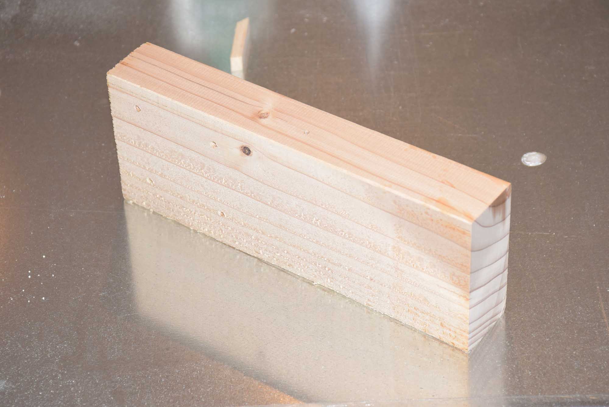
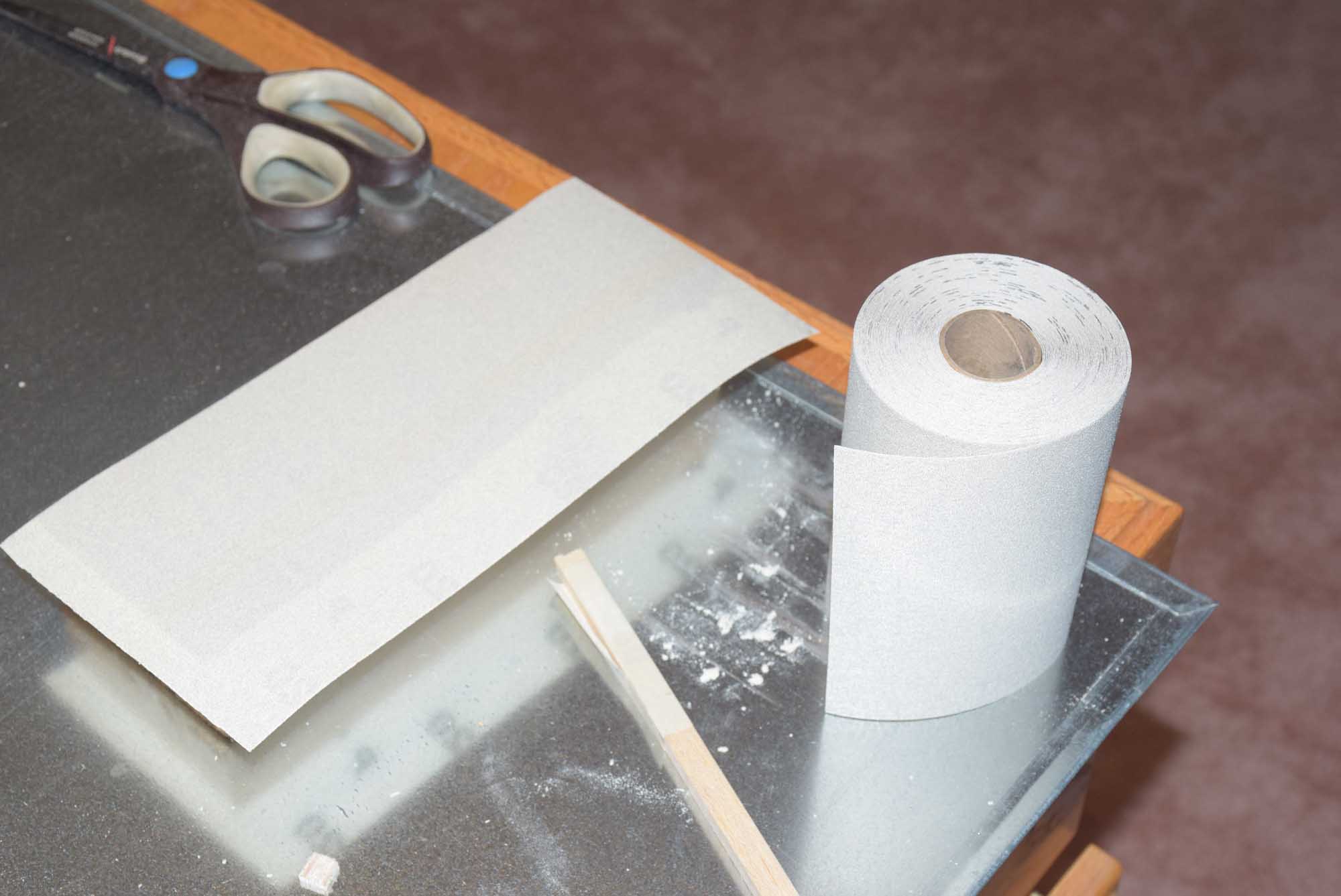
Once all the bracing is in place, it best to sand the parts to a uniform thickness.  I made a sanding block from a 2×4 about 10-12 inches long.  I ran this board through an edge jointer to make the sides and bottom very flat and square to each other.  I used 120 grit sand paper to get the material to a uniform thickness and then finished with 320 or greater for a nice smooth surface.  When sanding balsa it’s not necessary to apply a lot of pressure, just let the weight of the block and sandpaper do the work for you.  Also rotate the piece often so you don’t over-sand one particular.  It is also a good idea to sand in alternate directions.  All in all I probably removed only about 1/32 of an inch of material!

Horizontal Stabilizer
The horizontal stabilizer was built much the same way as described above.  I started with gluing in the main center parts and working from the middle outward.  Make sure the hinge line is a straight as possible here too!

The internal bracing was done the same way – using a razor blade to accurately mark the proper angle on the balsa stick and then sanded smooth with a disc sander.

Once all the parts were in place I added some weight on top and let it fully cure before sanding it to a uniform thickness.

Once these parts were all fully dry I set them aside to wait their turn during final assembly!

Stay tuned for part 4!


Sig J-3 1/4 Scale Cub Build Series – Part 2 – Rudder

Part 2 – Rudder

The Sig 1/4 Scale Cub build series is well under way! In part two of this build series, we will focus on the rudder assembly. Last time in part one we built the main fuselage formers and also the rear formers F8 through F11. If you have not seen part one, click here to view part one of the Sig Quarter Scale Cub build series.

As with any build that I start, I like to begin with the simple aspects of the build. For example, the rudder is usually a piece that can be framed up fairly quickly which helps to give a sense of accomplishment right a way. This goes a long way in helping the builder stay motivated during the entire construction process!

For the rudder I also tile printed that portion of the plan and taped the pieces together and covered them in wax paper. In this case it’s a matter of finding the correct printed parts mentioned on the plans and utilizing some of the straight balsa stock included with the kit. For a few of the straight pieces in the rudder, you will have to cut and shape these by hand using the balsa stock provided. Most of the curved parts of the rudder are included on a printed sheet of 3/8” balsa. Be sure to make note of proper thickness and width of the balsa stock the plans call for.

DSC_7170

The best way to cut out the printed parts is to use a small bench-top band saw and cut them to within 1/16th inch of the printed black line. Then shape the pieces accurately to the line using a disc sander. Some shaping by hand will need to be done on some of the inside curves. Again, take your time here – a lot of test fitting over the plans to make sure everything is within the lines!

DSC_7174

Once all the parts are cut out, lay them over the plans to test the fit. Once you are satisfied with the fit of the parts, I like to tack them together using thin CA. Use a magnetic building board or pins to hold the parts securely as they are glued in place. Once the main parts are in place, work on the inner framing. To ensure that the angles are accurate, you can use a bent T-pin to score the under side of the stock to mark the angle it needs to be cut at on both ends. Next, cut it close to the line using a razor saw and then finish for a nice snug fit with a disc sander or sanding block. A disc sander will help to ensure the angle is square along it’s entire face.

Once all the framing is completed, I like to use my favorite wood glue and brush a small amount into any gaps that need filling. Some final sanding will be needed to finish the part for final assembly.

DSC_7180

Wood Glue in Joints


Stay tuned for Part 3!


Sig J-3 1/4 Scale Cub Build Series – Part 1 – Formers

Part 1 Main Fuselage formers and Rear Formers F8-F11

The Sig J-3 Cub Build is now under way!

One of the first parts that are easy to build are the main fuselage formers and the rear balsa formers F8-F11. You will have to build the main fuselage formers from the balsa sticks provided – cutting them to size according to the plans from the 36” stock provided. Rear balsa formers F8-F11 are die cut balsa pieces you will have to glue together at the seams.


Before starting the build, I like to sort the balsa and included ply wood die cut parts into piles. With the Sig RC48 J-3 Cub kit, much of the balsa is supplied as die cut, printed balsa sheets, or in the form of balsa sticks. It helps to organize things; when the manual calls for the needed parts, they will be easier to find.  Most plywood parts are already die cut and are easily removed from their sheets.

Sorting balsa

Before starting this build I decided to have all four plates of the plans scanned into PDF. This allows me to print out certain parts without having to cut up the original plans. I print them out using the tile feature in Adobe’s Acrobat PDF viewer software. I also print them with a ½ inch overlap. This allows me to line up the tiled sheets much more easily. I tape them together using small pieces of Scotch tape. Using a large window as your background allows you to see through the pages allowing you to line things up perfectly as you tape them together!

Sig J-3 Cub Formers Template

I like to build off my magnetic building board – that I use for all my model building –  to ensure the parts are aligned as accurately as possible. Take extra time to make sure the main fuselage formers are square, will result in an air frame that is precisely built and accurate. Remember straight air frames fly better and helps to reduce any trimming issues!

Build the main fuselage formers as shown directly over the plans. Use a good wood glue or even epoxy here. Using slight pressure on the joints (using the magnets you can “wedge” the parts together as they dry) will result in a very strong and sturdy joint! Add some weight on the pieces that glue on top of the former sides to ensure a good bond.

Gluing up the formers. adding weight on glue joints

Glue the rear former halves F8-F11 together using wood glue and tape on one side to ensure the seams are pressed tightly together while they dry. Place some wood glue in the seam, and then press the joint together by hand and wipe out any access glue that seeps out. Finally, place the formers in between to pieces of wax paper as they dry. Add some weight on top to ensure they dry straight and flat.  Use a piece of scrap board and a ten pound dumb-bell as weight on top of the formers.  The scrap wood board will help distribute the weight evenly over the formers.

Once the glue has dried the formers are now complete!  They may require some final sanding once mated to the fuselage sides.


Have a question or comment?

If you have a question or comment, please feel free to email us at the following address: [email protected]

Other Information