Monthly Archives: February 2016

Sig J-3 1/4 Scale Cub Build Series – Part 8 – Rear Formers

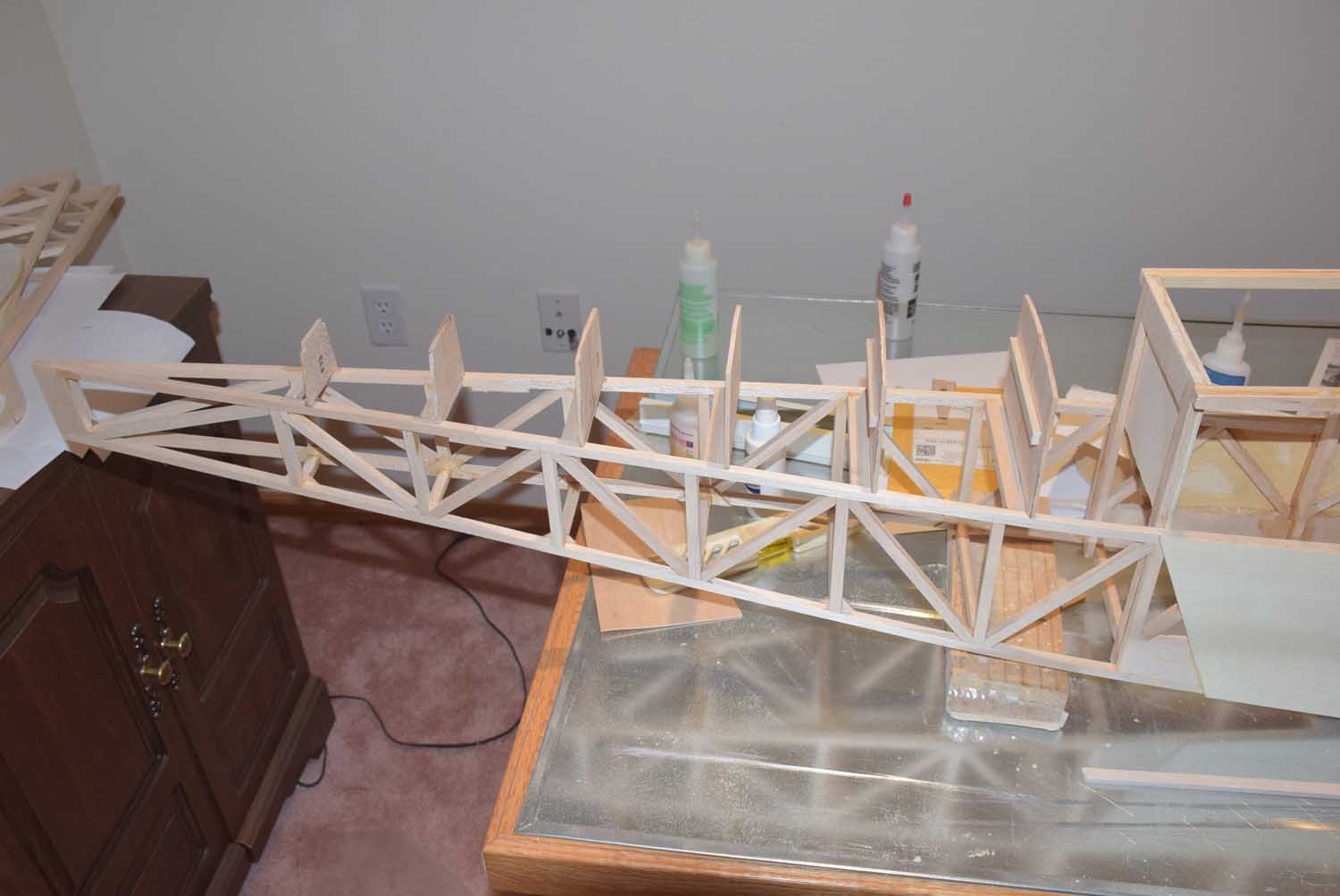
In part 8 we will take a look at installing the rear formers along with the top stringers.

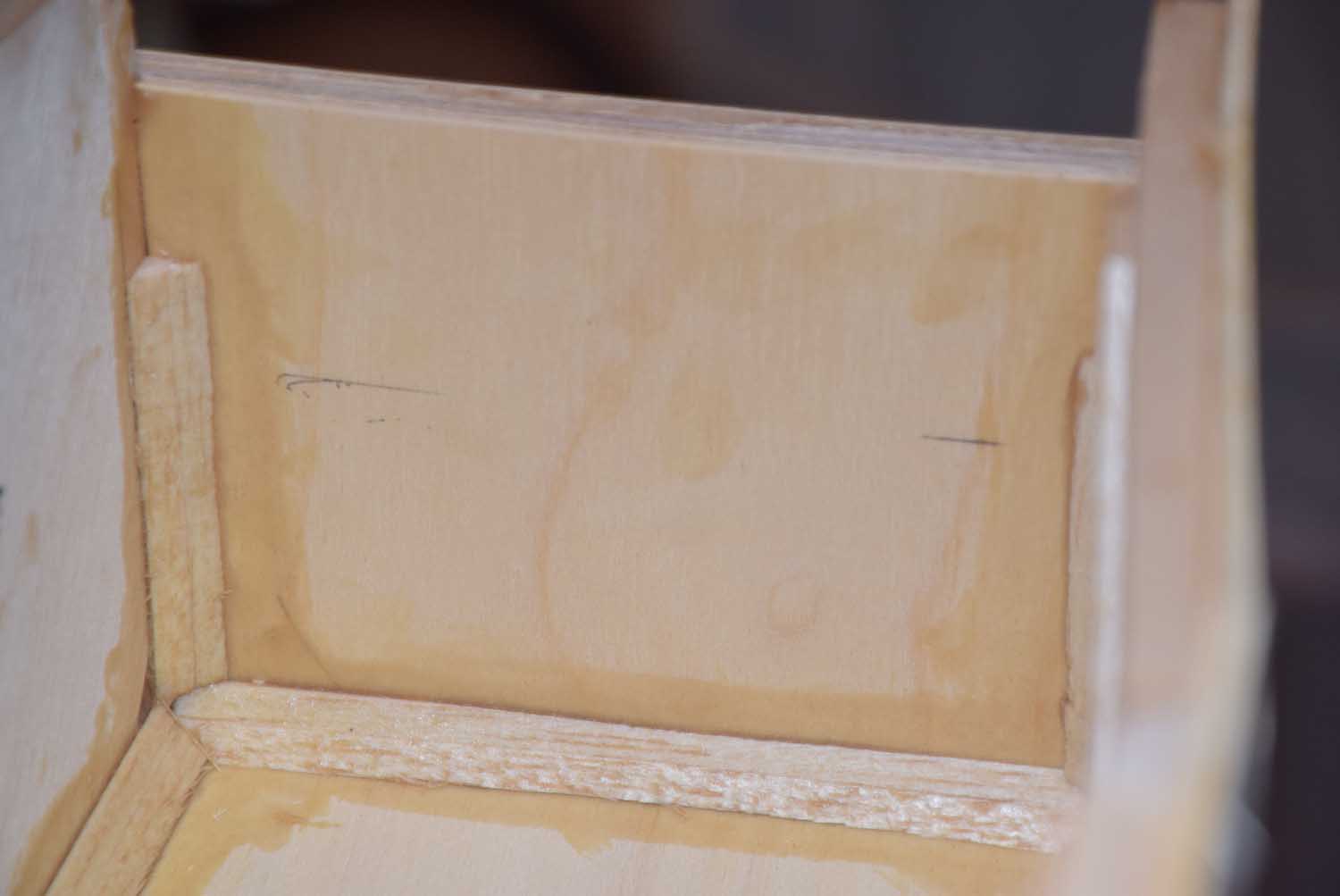
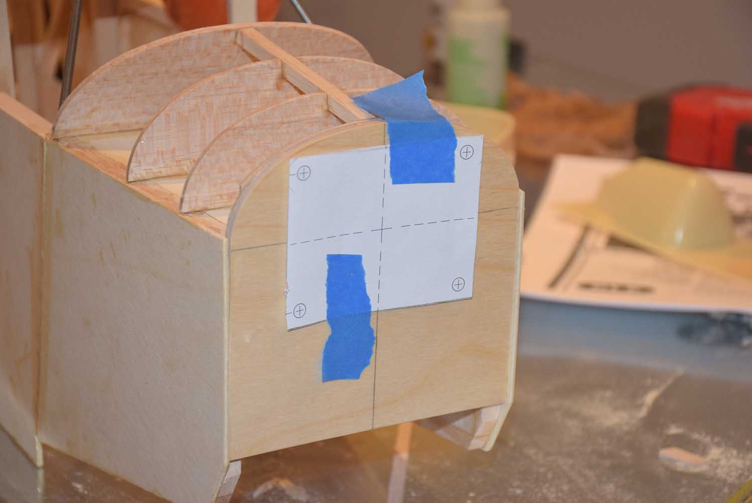
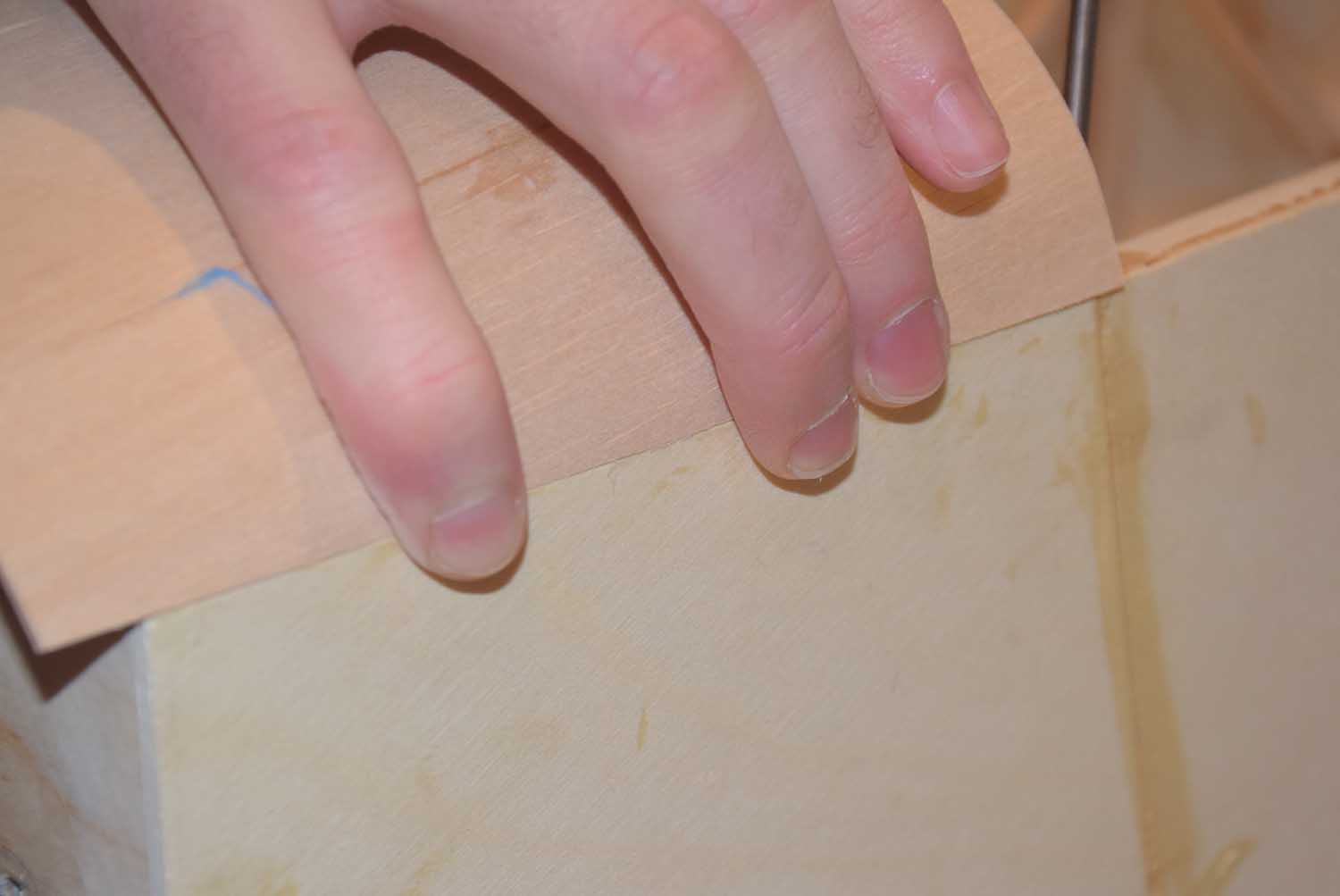
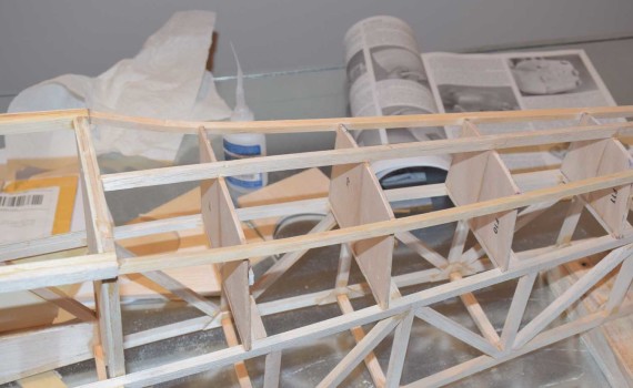
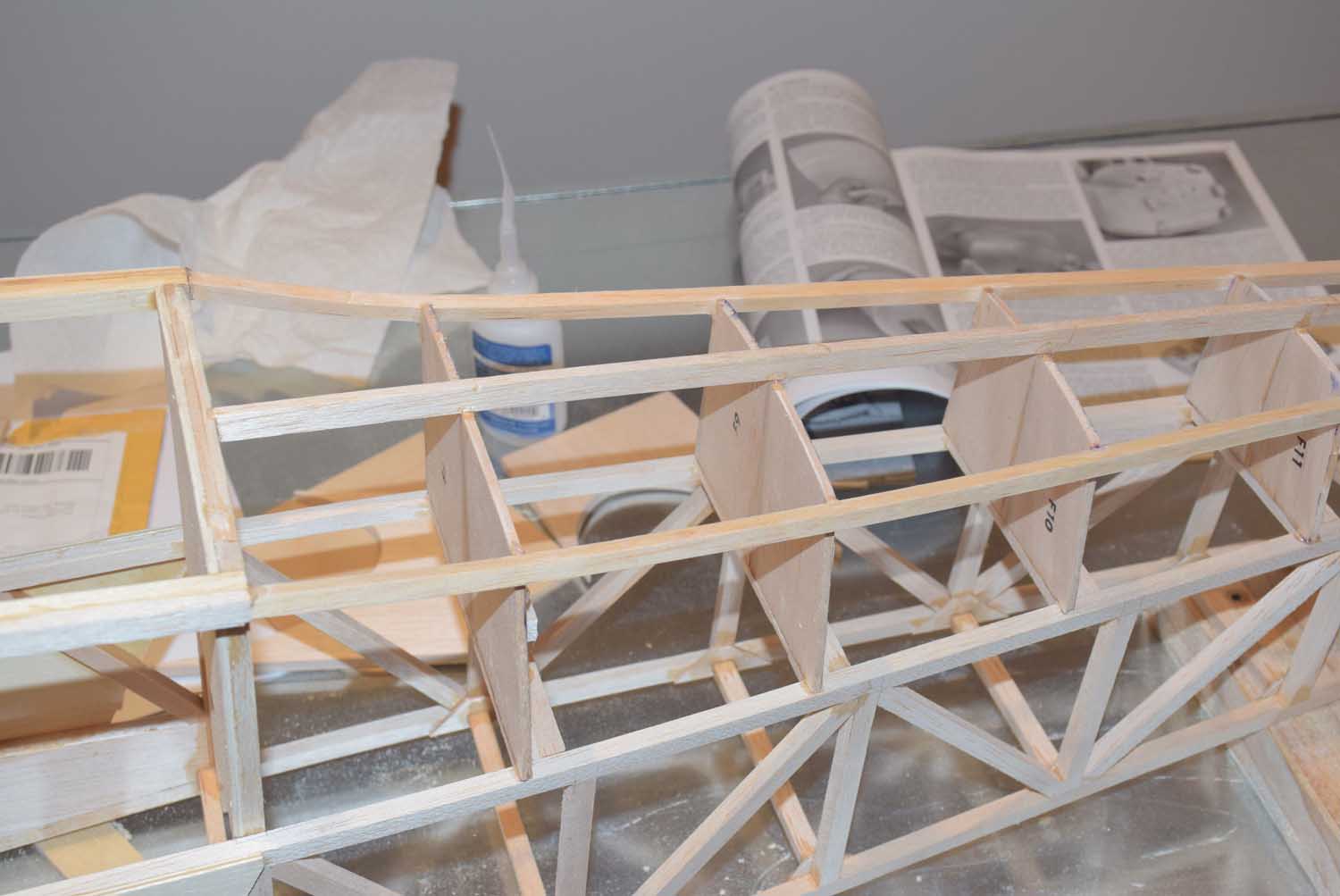
In the photo below you will notice I added some additional cross pieces, this will be used to add in some small reinforcement blocks when gluing the rear formers in place.

DSC_7519

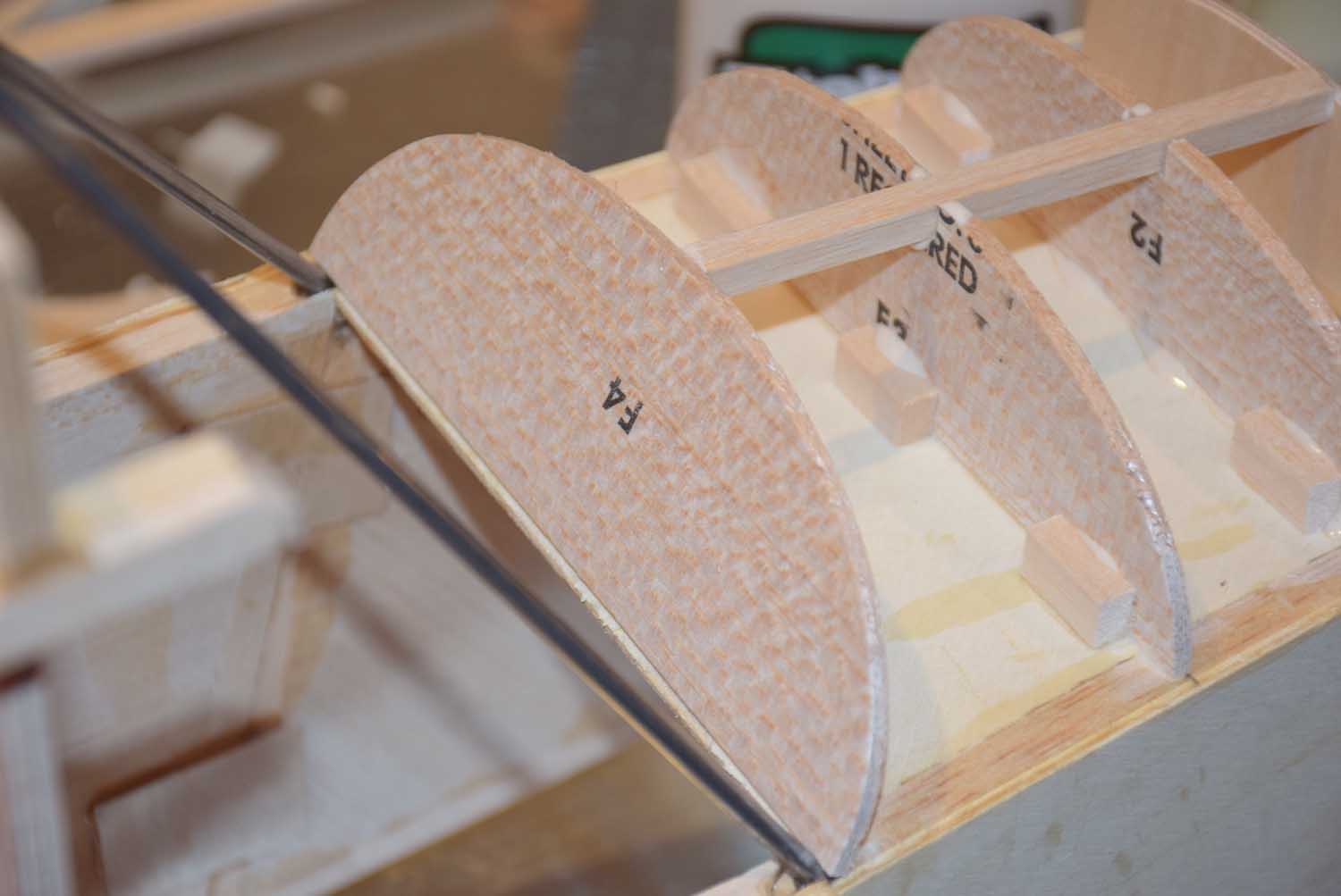
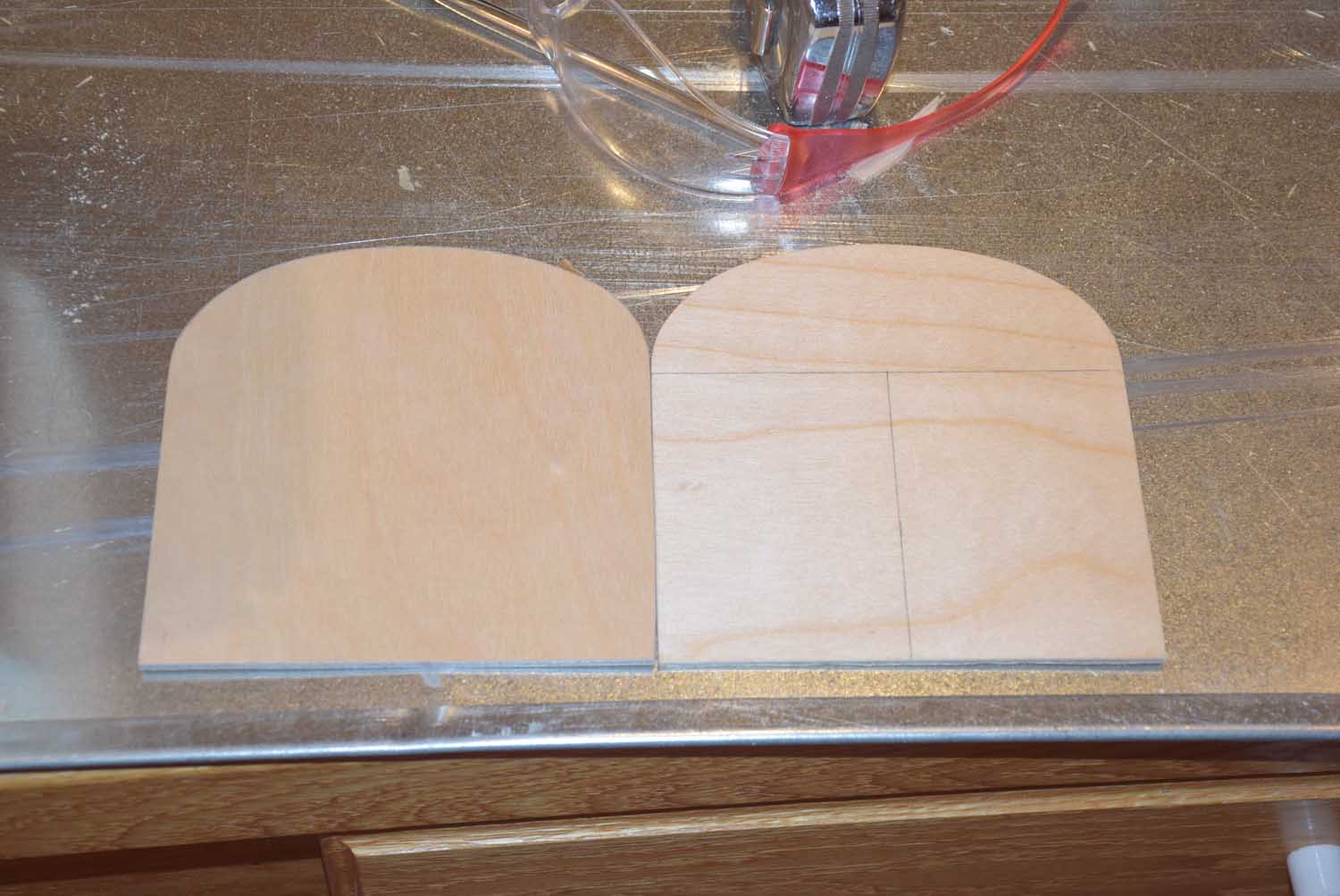
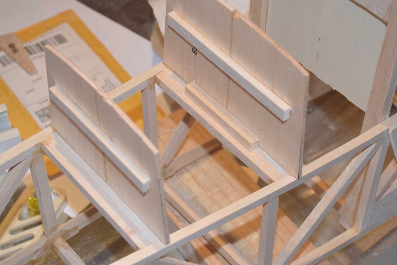
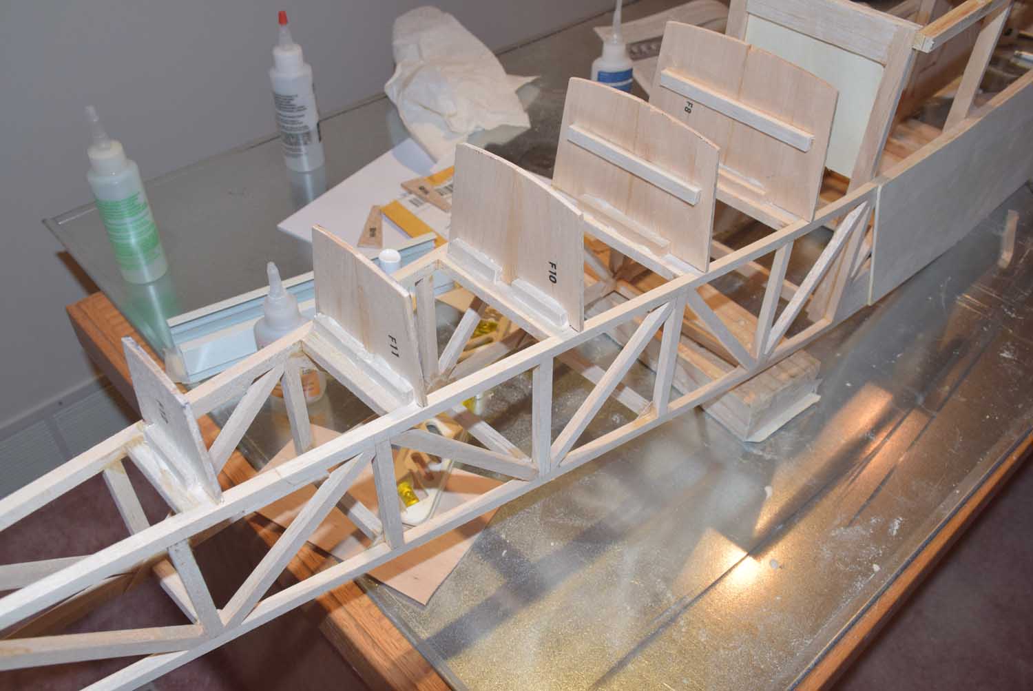
The formers F8-F13 are included with the Sig kit as die-cut balsa. A couple of the larger formers are in two pieces; you will need to glue these together and add a small cross piece for extra strength. (shown in photo above)

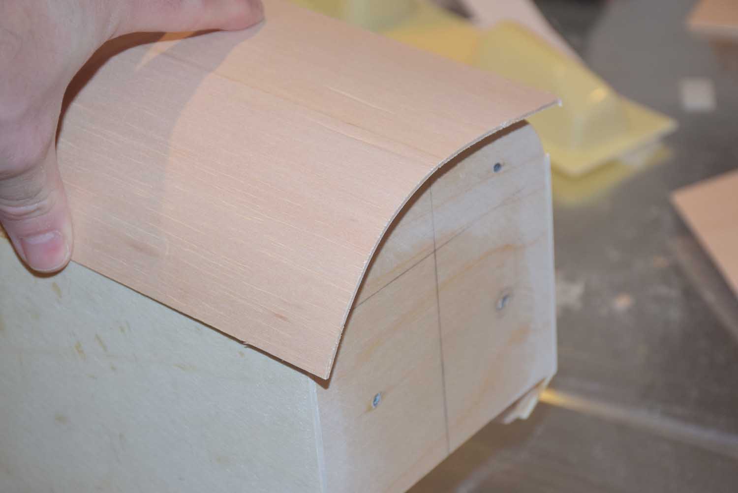
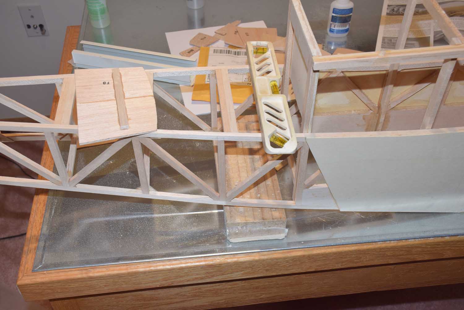
Next, begin by gluing in the largest former and working your way back toward the tail.  One thing to note, it is important to line the fuselage up as described in the manual.  The formers will be glued in at a small angle relative to the ground.  What I did was prop up the fuselage at the required angle with some blocks. Use a small torpedo level to glue the formers in at a 90 degree angle.  Using this method will automatically account for the proper angle.

DSC_7520

DSC_7522


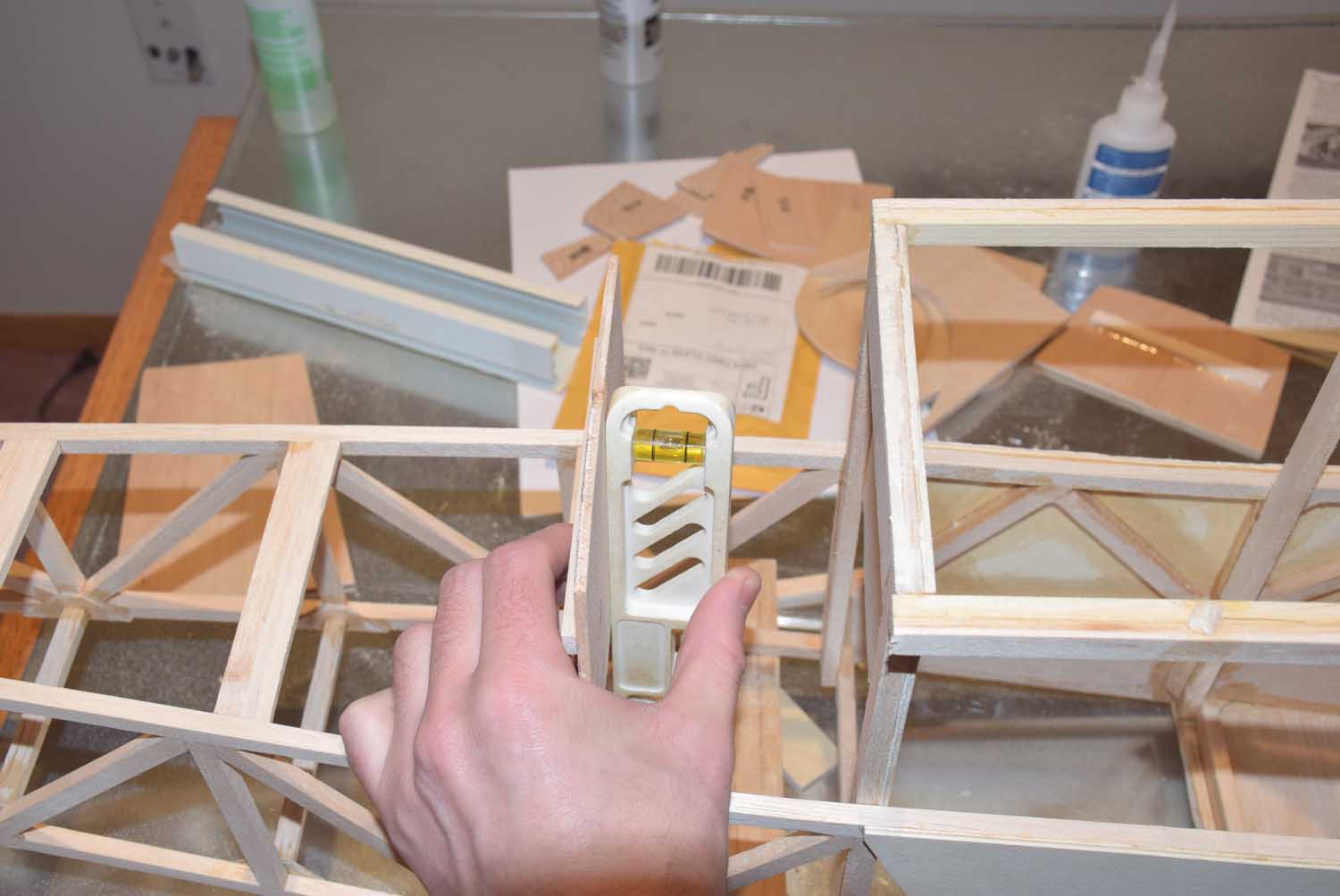
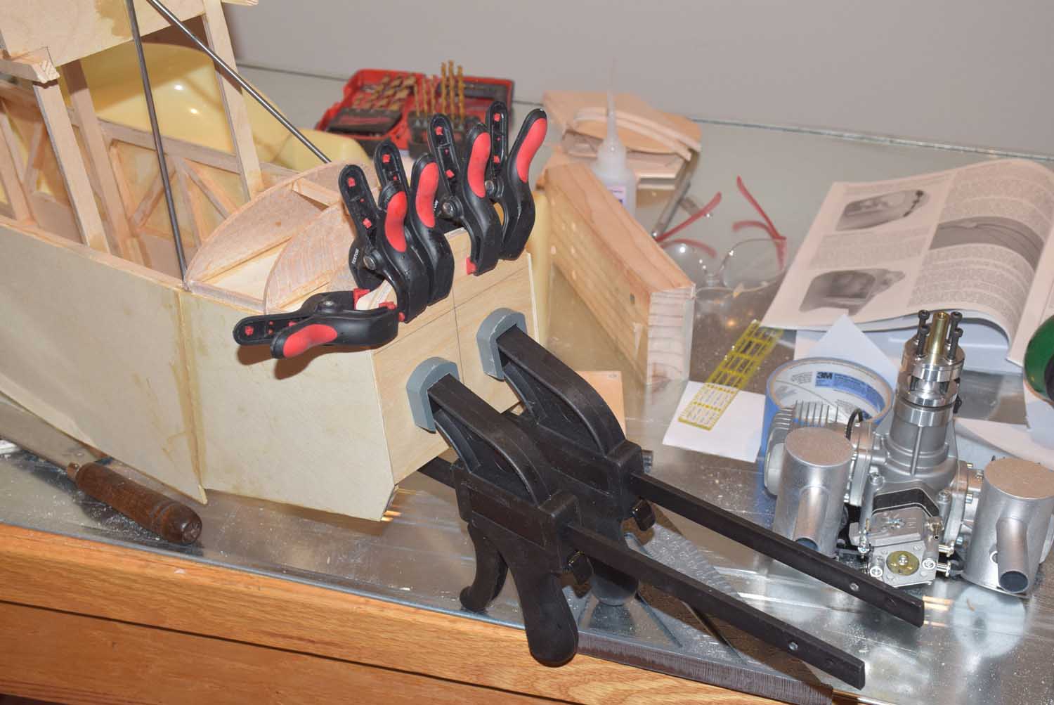
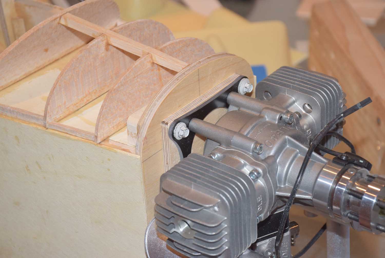
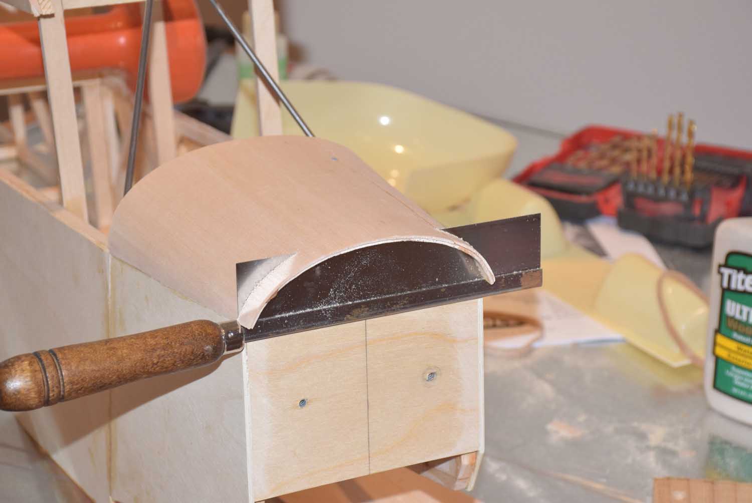
Once all the formers are glued in place, I added some additional blocks behind each former for a some extra support.

DSC_7523

DSC_7524

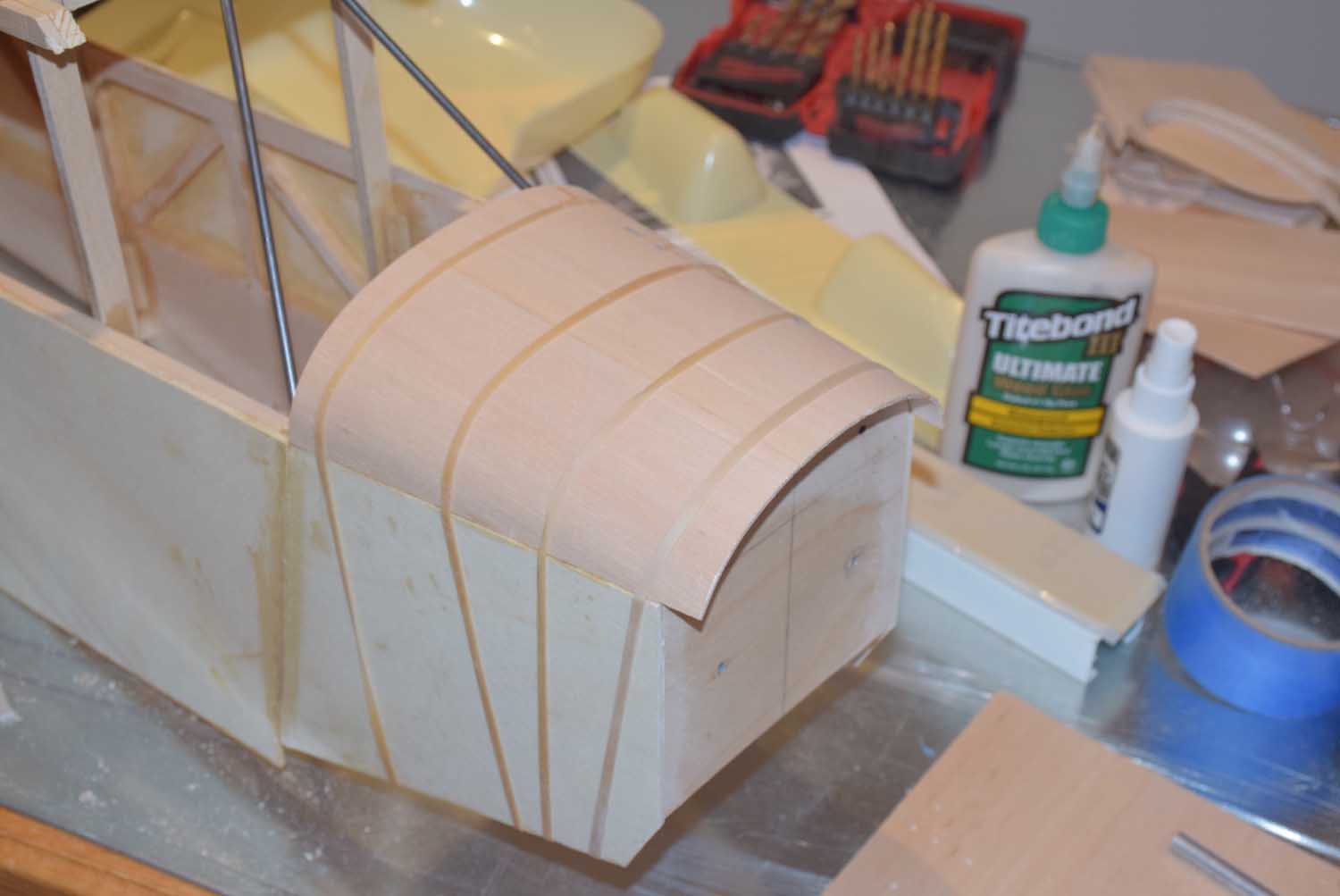
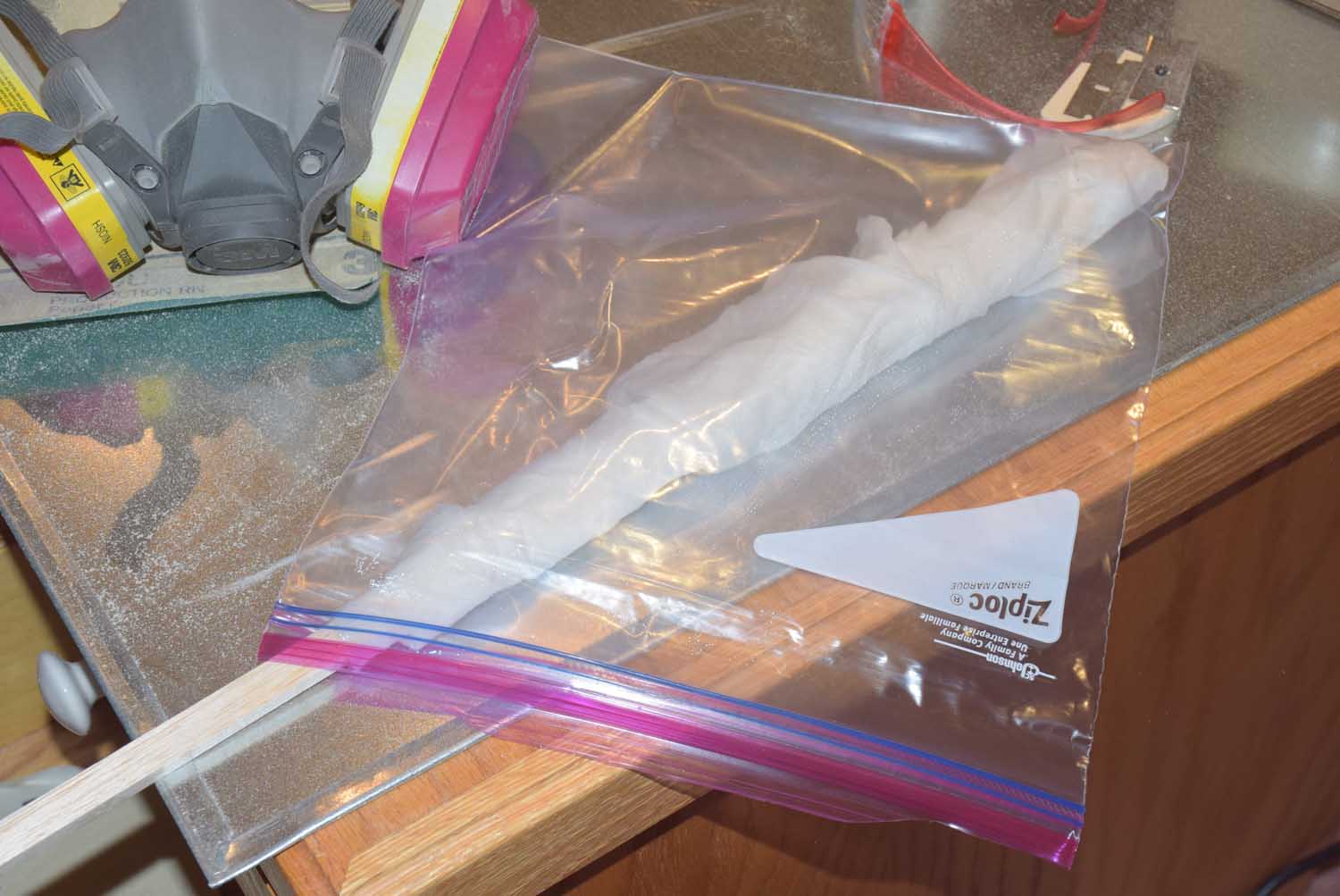
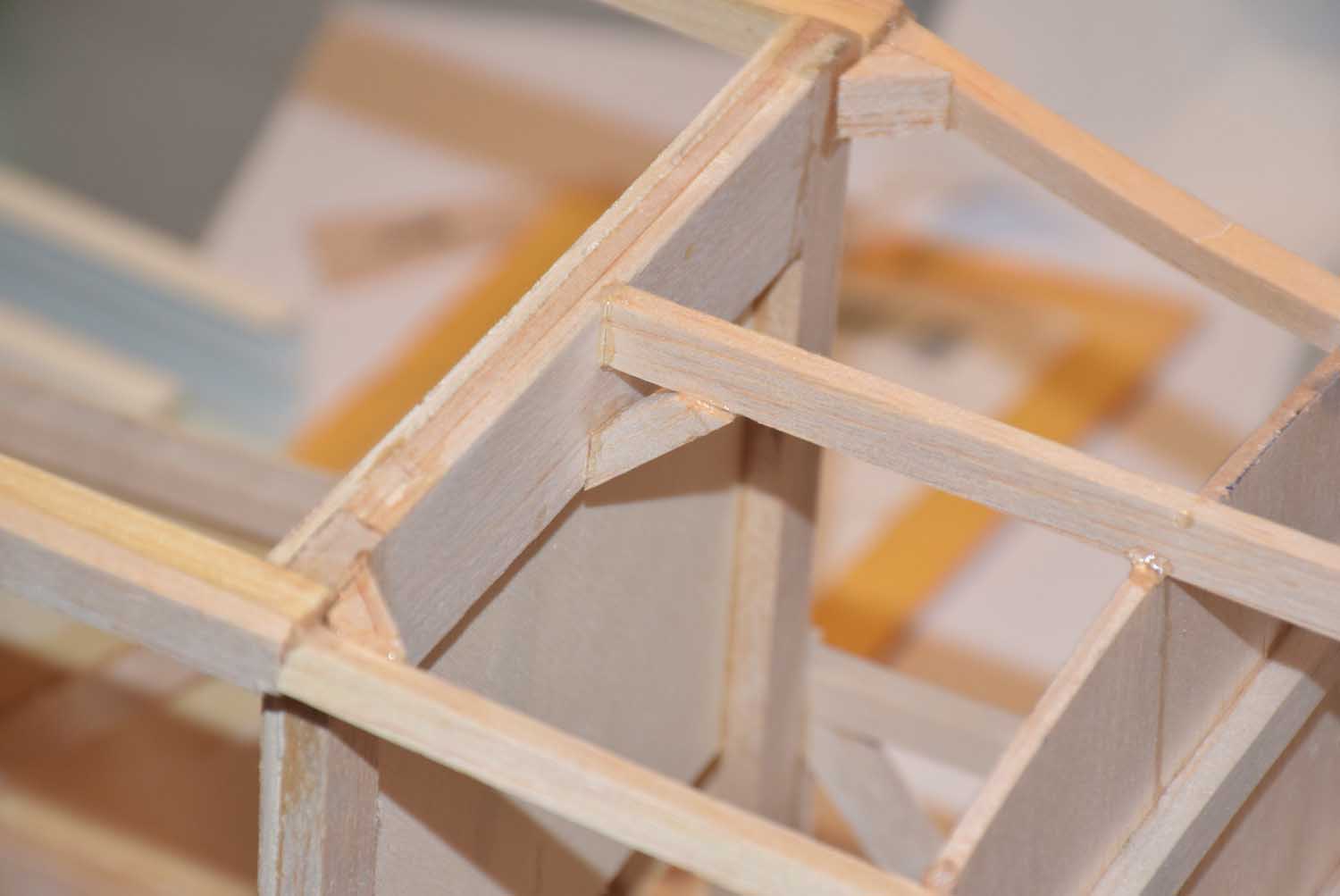
I let these dry overnight before adding the top stringers.  The top stringers require you to bend a curve into the 5/16 square stock in order to meet the rear of the cabin.  I soaked a paper towel in water and then wrapped the last 12 inches or so of the square stock with the wet towel and placed the ends into a plastic bag.  It only required about a 30 minute soak to make them soft enough to work with.  I used thick CA here and some kicker so I could quickly get them into position.

DSC_7518

DSC_7526


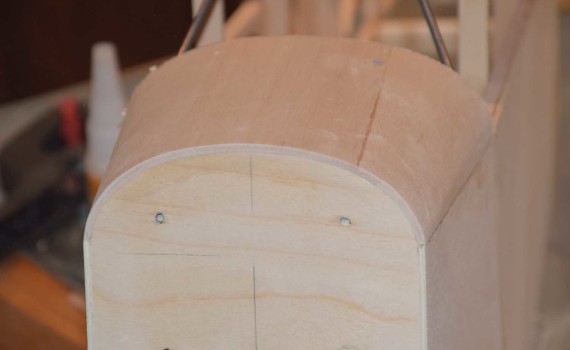
I also added in some additional reinforcement blocks where the stringers meat the rear of the cabin.  This will help hold it more secure.

DSC_7527

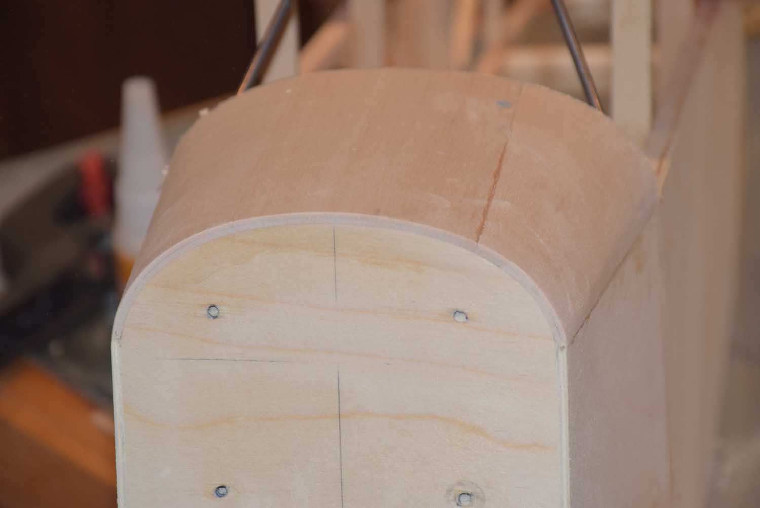
This was a little shorter build article, but once you see the formers in place the fuselage really begins to take shape!

In part 9 we will be taking a look at building a few miscellaneous items: putting in the cabin floor, adding some triangle balsa in the nose, installing the fuselage side stringers and window fill-in posts.


Sig J-3 1/4 Scale Cub Build Series – Part 7 – Nose Section Formers, Firewall & DLE 40 Twin Motor Mount

In part 7 we will be installing the nose formers and sheeting, the engine firewall and making a motor mount spacer for the DLE 40 twin cylinder gas engine.

Start by finding the nose formers from the die cut balsa supplied with the Sig kit.  Take measurements from the plans in order to properly place them on the nose section of the fuselage.  You will need formers F2, F3, and F4.

DSC_7477

You will notice in the above photo I added some additional scrap pieces of balsa to help hold the formers in place as the glue dries.  In the photo below, I also added a 3/8 piece of basswood just behind former F2,  this will give the engine mount bolts a thicker piece of wood to bolt to.

Also add a block of wood behind the firewall under the nose area inside the cabin.

DSC_7496

Glue together the two 1/8 inch thick die cut plywood firewall pieces together and allow to dry.  Make sure you use a enough glue so it squeezes out of the edges, we want a good tight bond here!   Wipe of any access as you add clamps around the edges.  Set aside and allow to dry overnight.

DSC_7479

The DLE engine manual provides a drilling template that helps determine the placement of the DLE twin cylinder engine on the firewall.  Tape this in place on the firewall lining it up with the thrust lines you transferred from the plans.

DSC_7490

Once the firewall is dry, you can now glue it to the main fuselage.  Test fit and sand as need for a nice easy-snug fit.  Once satisfied with the fit, use clamps and glue this in place.

DSC_7498

Once the firewall has been installed, we will need to make a couple of spacer blocks for the DLE 40 twin engine to allow enough clearance for the mufflers.  Use the provided drill template to cut some spacer blocks and drill holes for the bolts you will be using large enough so they can slide through easily.  Now is a good time to drill the holes on the firewall and test fit the engine.  I ended up making two spacer blocks for just a little more clearance.

DSC_7501

Once satisfied with the fitment of the engine, we can move on to sheeting the nose formers F2-F4.  The kit supplies some 1/8 thick balsa for this.  However, I found it easier to use two layers of 1/16 balsa.  Use wood glue in between the layers.  Use a number of rubber bands to hold the sheeting securely in place as it dries.

DSC_7510

DSC_7508

DSC_7503

Once the sheeting is fully dry, trim the excess with a razor saw and sand smooth.

DSC_7512

DSC_7513

DSC_7514

That’s it!

In part 8 we will be installing the rear formers!  Things are really starting to take shape!


Have a question or comment?

If you have a question or comment, please feel free to email us at the following address: [email protected]

Other Information