Sig J-3 1/4 Scale Cub Build Series – Part 13 – Finishing and Covering.
Category : Uncategorized
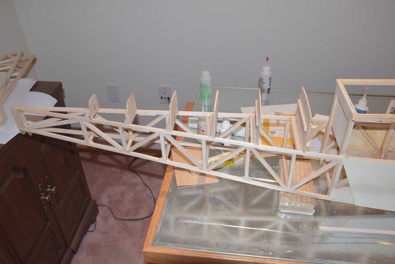
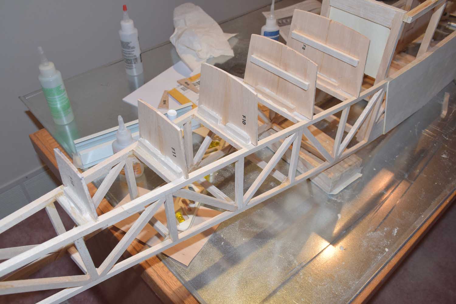
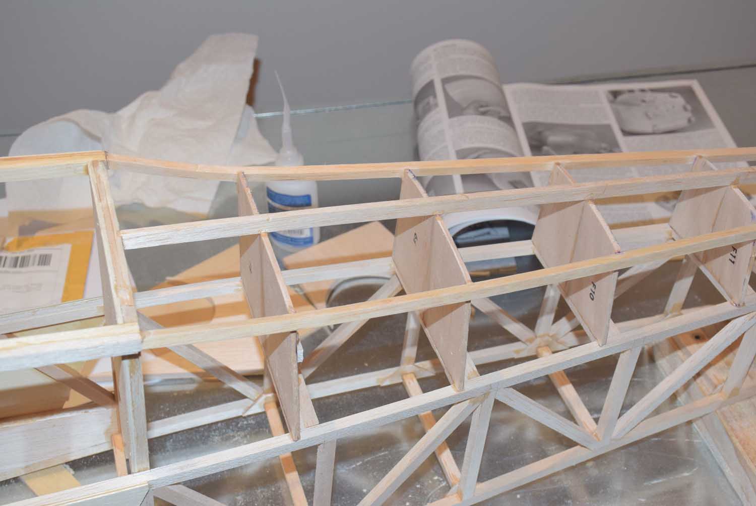
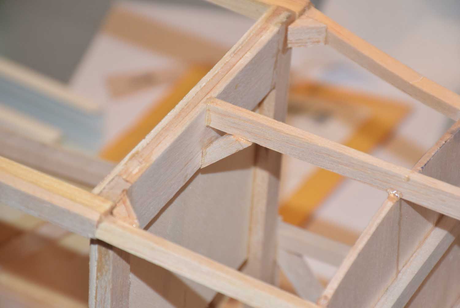
With the wings completed in part 13 of the Sig 1/4 Scale build series, we were left with an air frame that is now ready to be covered!
For this build, I opted to go with a color scheme other than yellow! I know, I can’t believe it either! Part of the reason for not sticking with the traditional Cub yellow color scheme was to avoid confusion in the air with the other yellow cubs in our club!
I decided on a rather simple three color scheme of bright red, white, and some gray for an accent color. I covered the plane using the Hobbyking branded covering and I was quite pleased with how easy it was to work with and how well it formed around curved surfaces!
Another benefit of the hobby king covering is standard rolls around roughly 5 (15 feet) meters long and around $10 a roll!
https://hobbyking.com/en_us/hardware-accessories-1/covering-film.html
Just a couple of quick tips when applying covering film:
- Start with the “bottoms”; this includes covering the bottom of the wings first, bottom of the fuselage, then work your way up to cover the sides and finally the top.
- Use razor blades for cutting the excess covering instead of xacto blades as these blades seem a little thinner and sharper!
- If you are overlapping colors, make sure the overlap is at least a 1/4 inch over the first color and preferably over a fully sheeted area. This will ensure a nice tight seal.
- Also keep in mind any overlap seams in relation to air flow. You will want the leading edge of a wing to “overlap” the first color. This prevents the airflow from eventually working the seam loose.
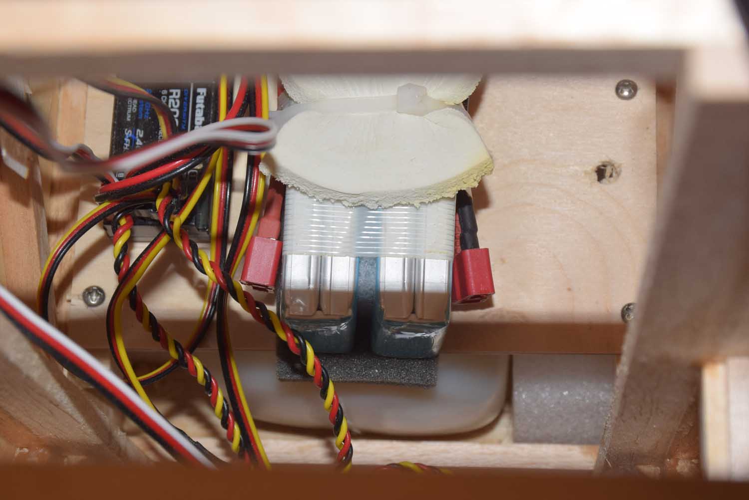
Electronics Used:
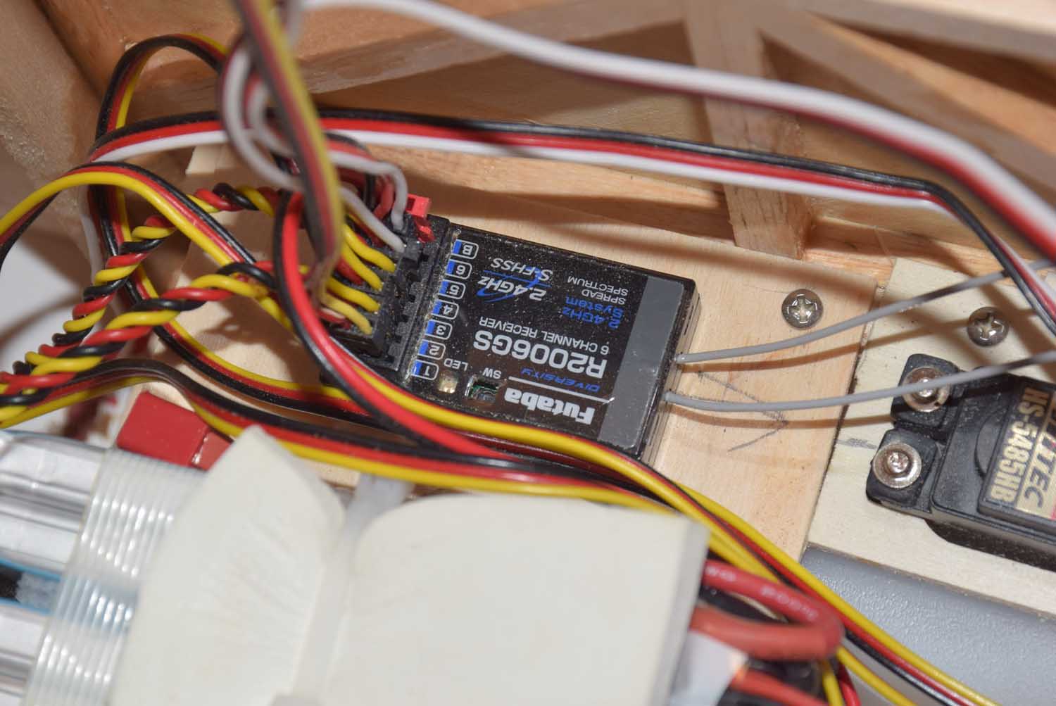
- Futaba 6 channel RX
- two 2-cell LiPo 2600 MAH (make sure your servos and RX are rated for 7.4 2S voltage)
- Hitec HS5665MH Servos for control surfaces
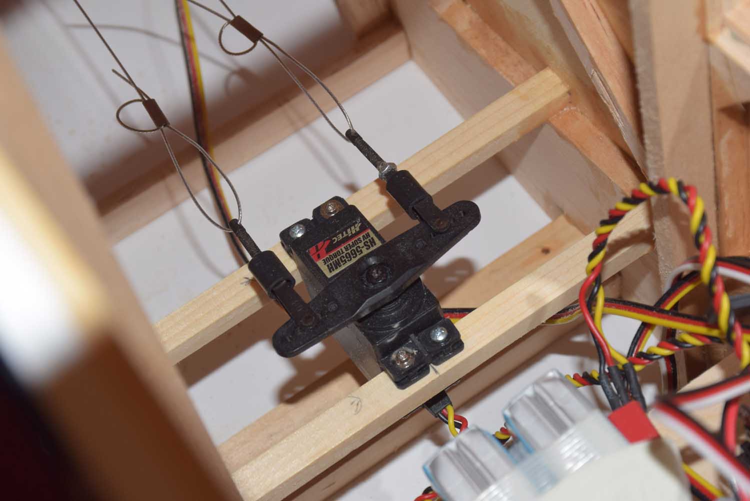
- Dubro Large Scale pull-pull rudder system.
- Hitec Large Servo Horns.
- Dubro 4-40 clevis and rods
- Great Planes large scale control horns.
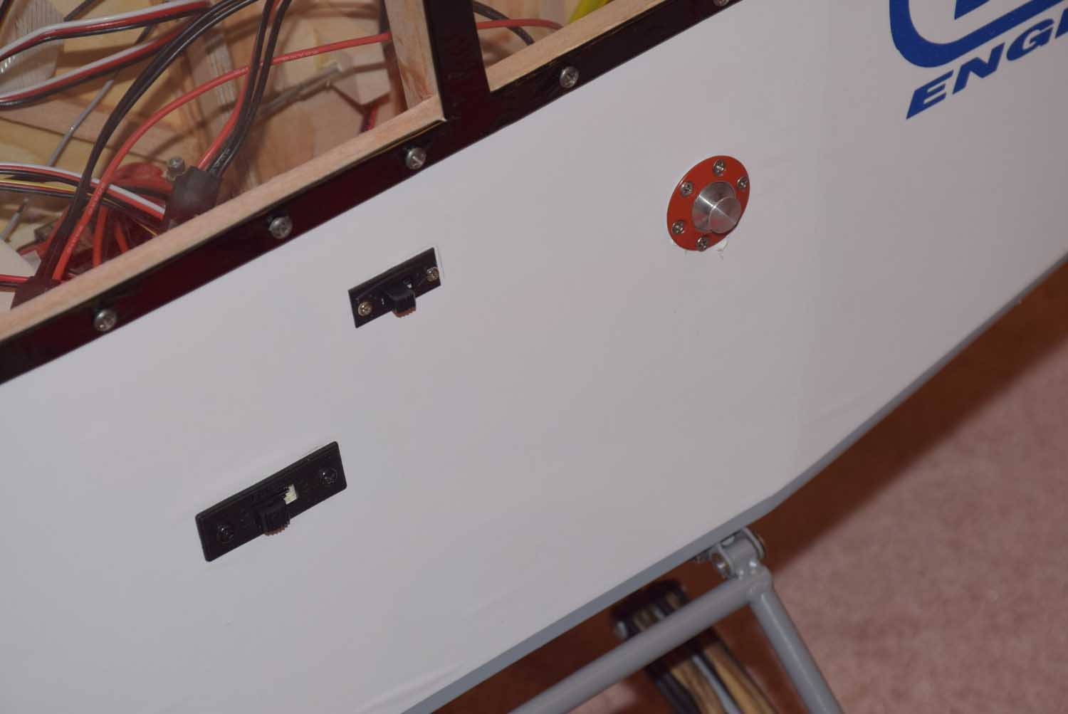
- 2 Switches in combination with 2 cell LiPos above. Each power system is separate. One for the RX and servos, and one for the DLE 40 ignition.
- Dubro 20oz Fuel Tank
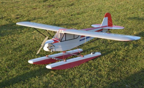
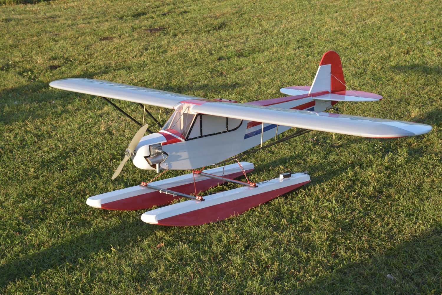
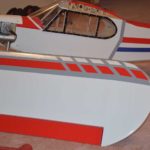
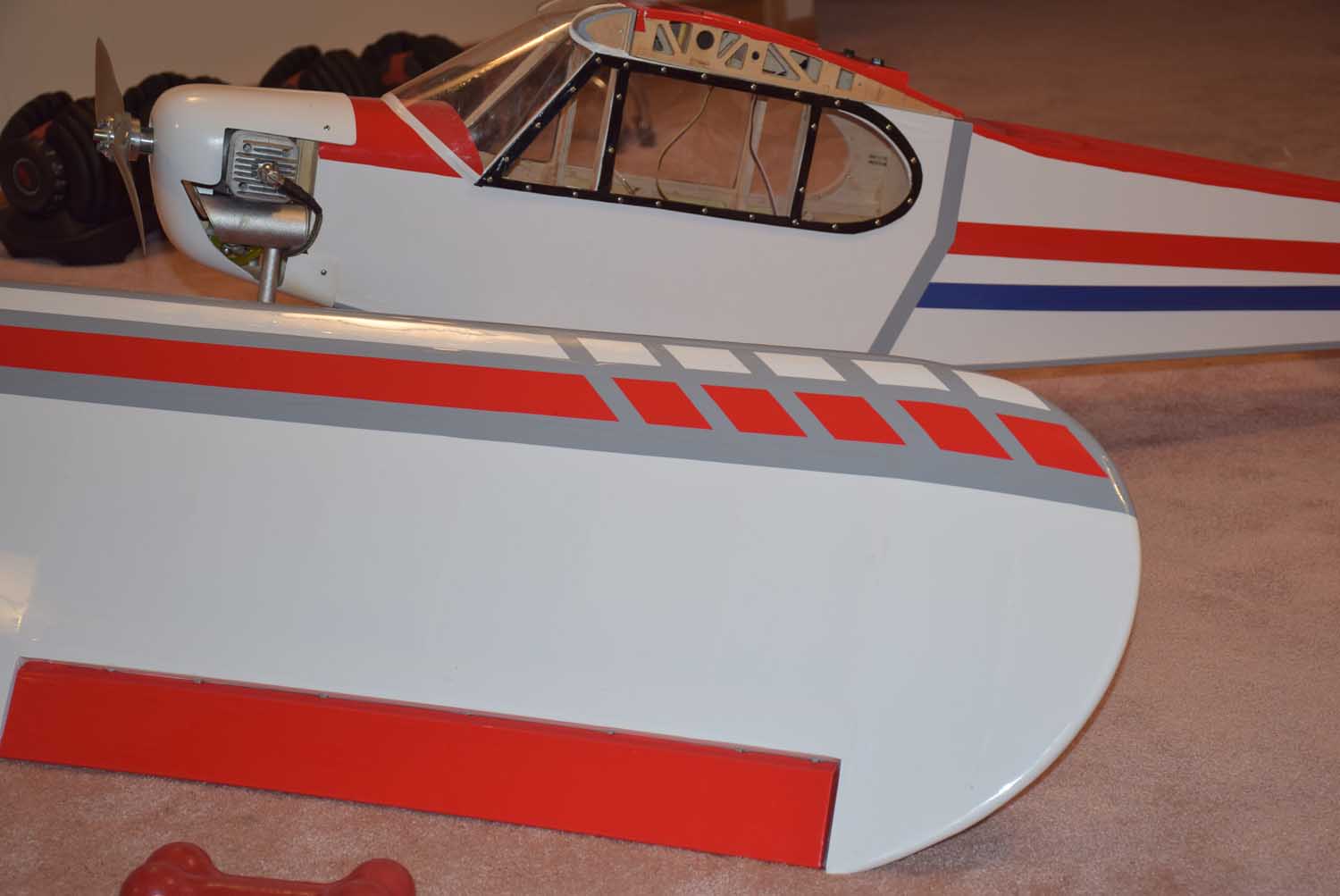
Here are a handful of photos of the finished product. The clear windows were added after the maiden flight! I’ve also included a few photos of the electronics setup for this plane as well.
A few parting notes:
You’ll notice the 20 oz gas tank is more centrally located as close to the CG as possible. Sig recommends the tank be put far forward in the nose. With the heavier DLE 40 engine this isn’t necessary. In fact, once all the electronics were in place, it was just a matter of moving the 2 RX packs around to locate the perfect CG! I couldn’t believe how well it worked out!
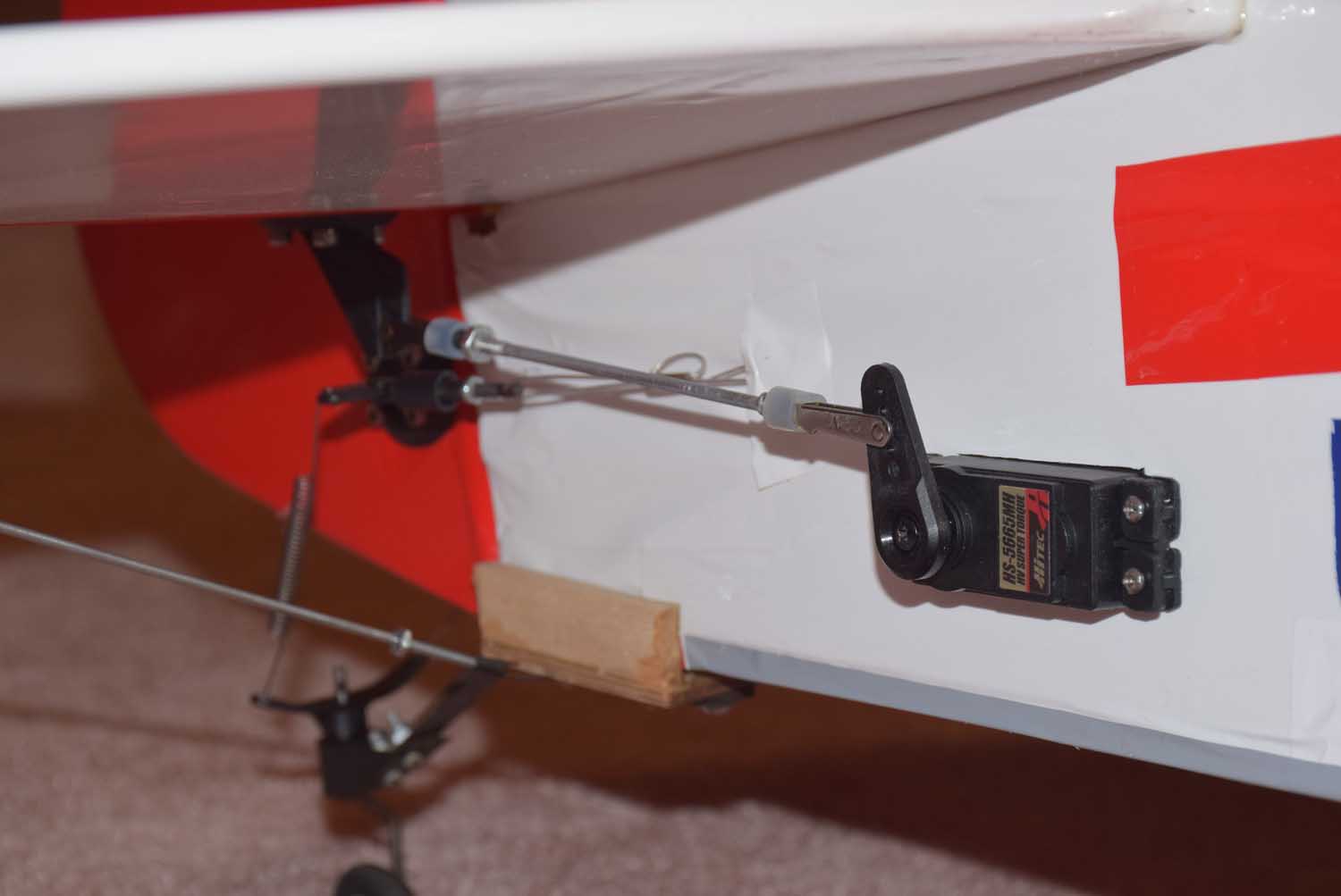
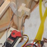
Also the elevator servo is mounted in the rear of the plane instead of running a long control rod. Take some precautions to seal this servo from water or use a water proof servo here.
-
- Ready for maiden!
-
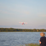
- Maiden flight off water!
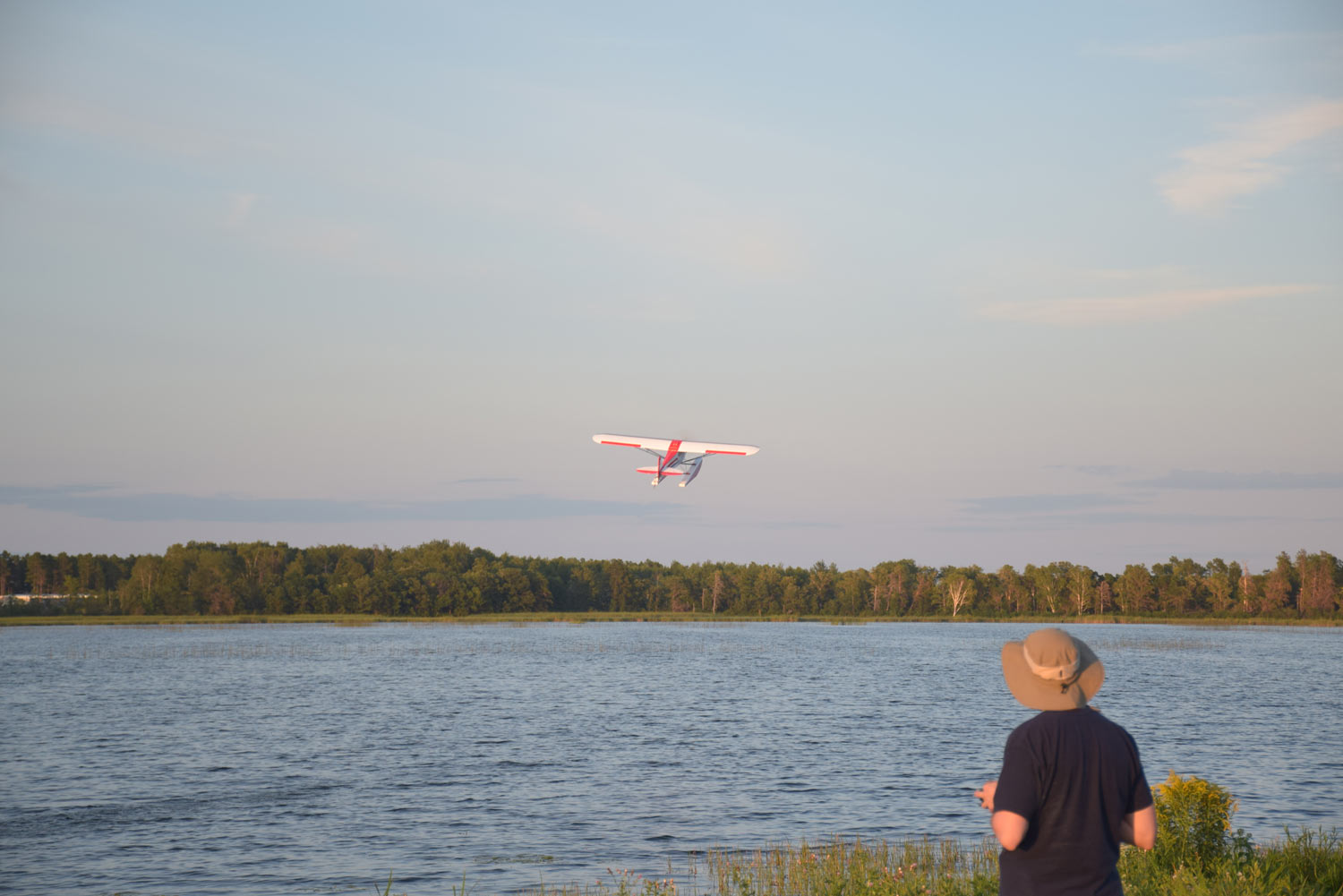
-

- Floats well!

-
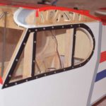
- clear windows and frames
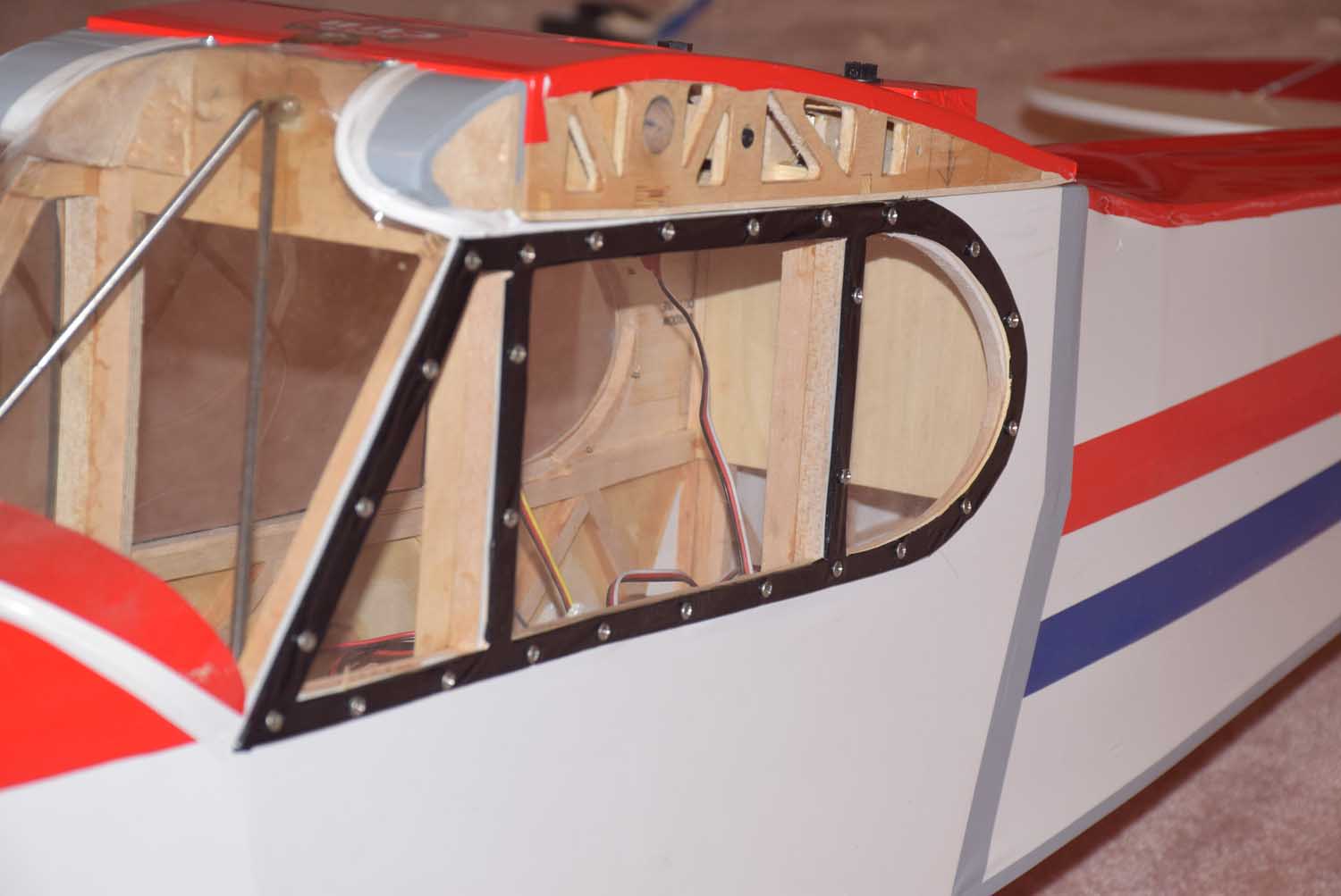
-
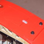
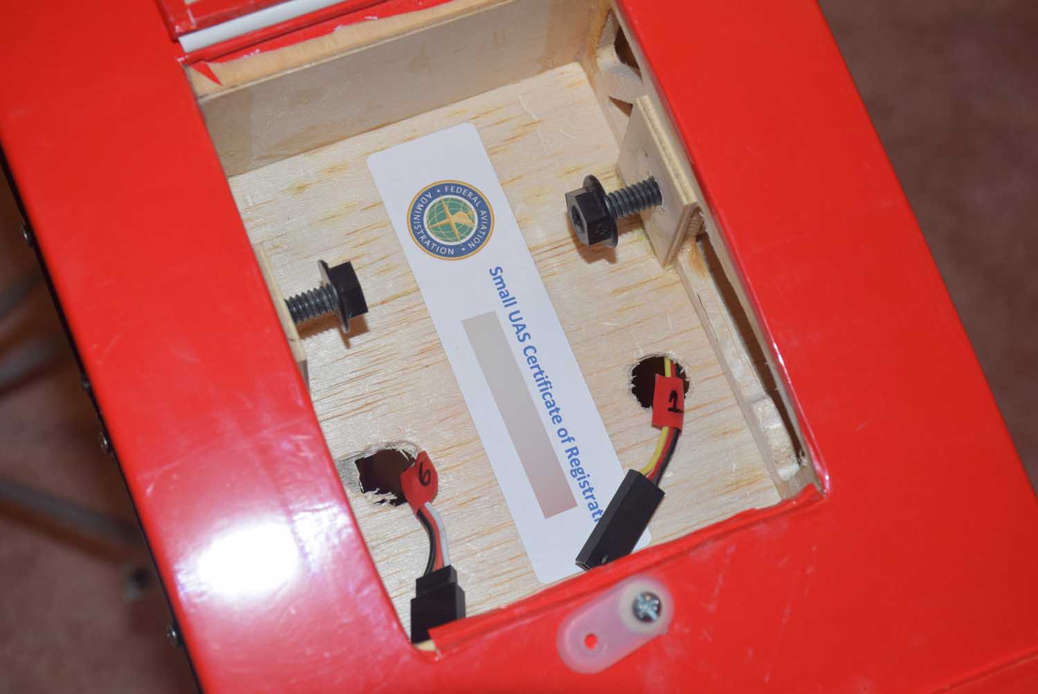
- easy access hatch for wing servos
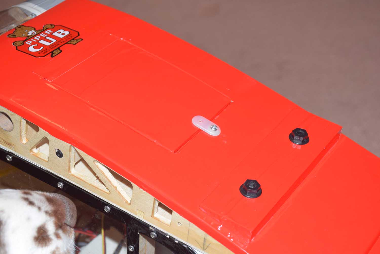
-
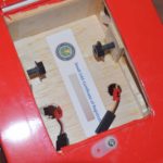
- easy access hatch for wing servos
-
- wing tip design and stripes
-
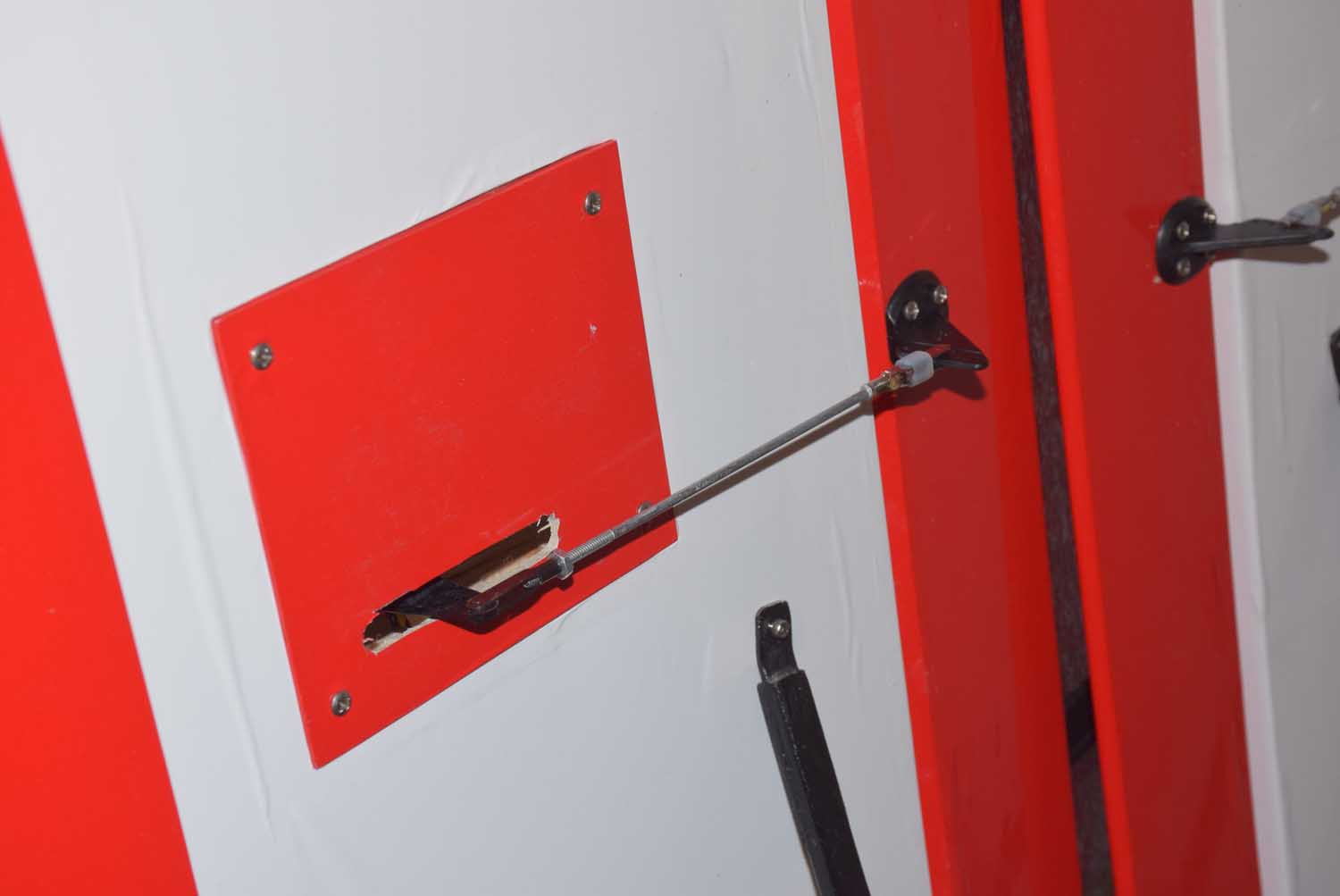
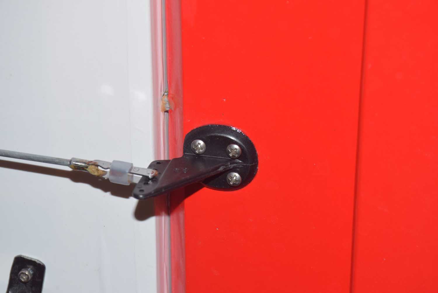
- Servo plates and Dubro 4-40 control rods
-
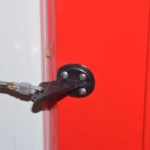
- Great Planes large control hors
-
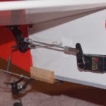
- Elevator servo mounted in rear of fuse
-
- Pull-pull rudder
-
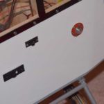
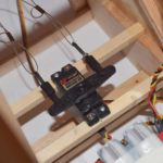
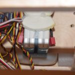
- two-switch setup
-
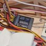
- Futaba 6ch RX
-
- Throttle cable setup
-
- 2 – 2S LiPos
-
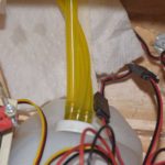
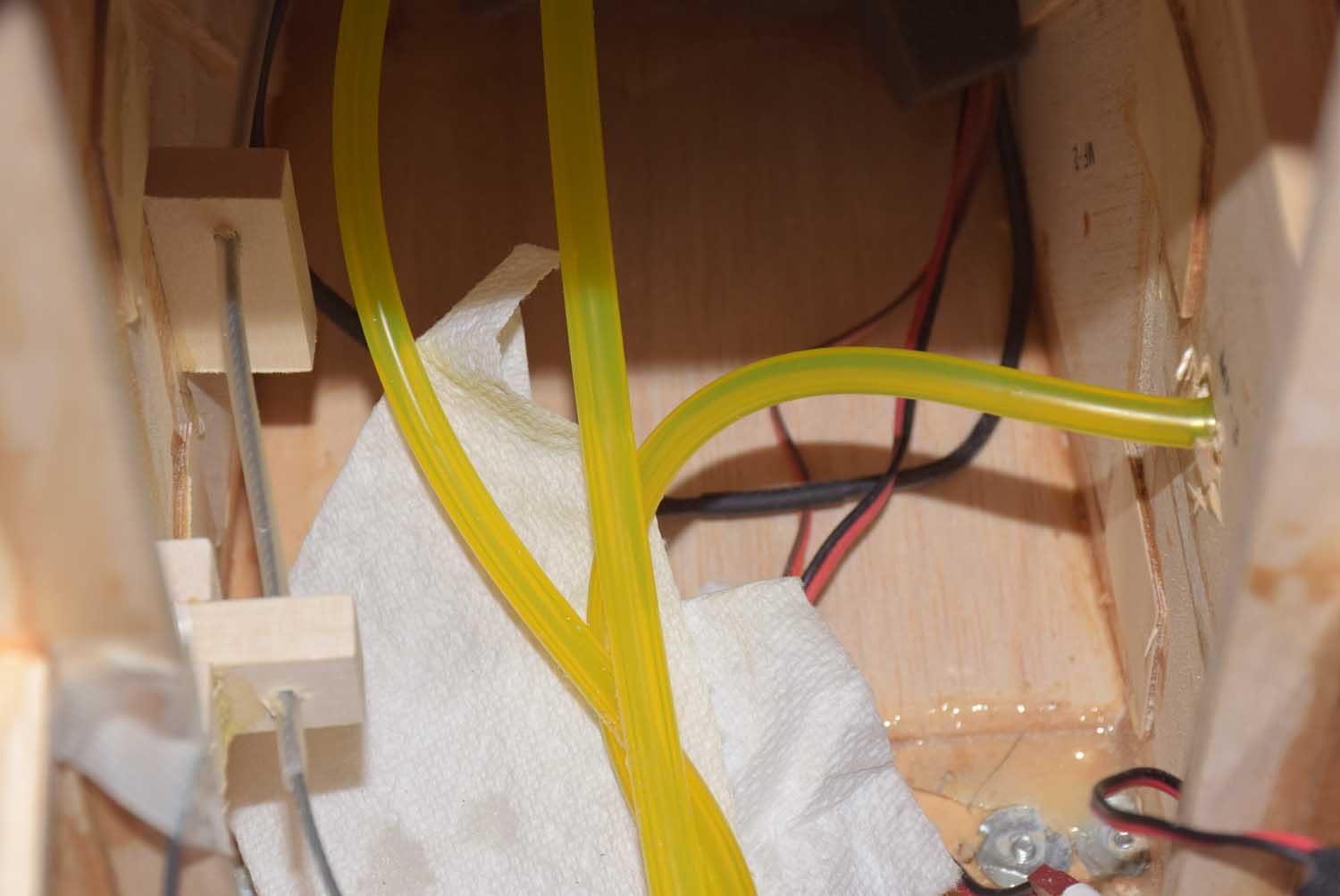
- 3 line plumbing
-
- 3 line tank plumbing – one line goes to fuel dot.