Ultra-Tote Field Box Modifications
Category : Model Airplane Building
In this write up we are going to take a brief departure from our J-3 Cub Build series and build the Hobbico Ultra-Tote Field box – but with a few customizations!
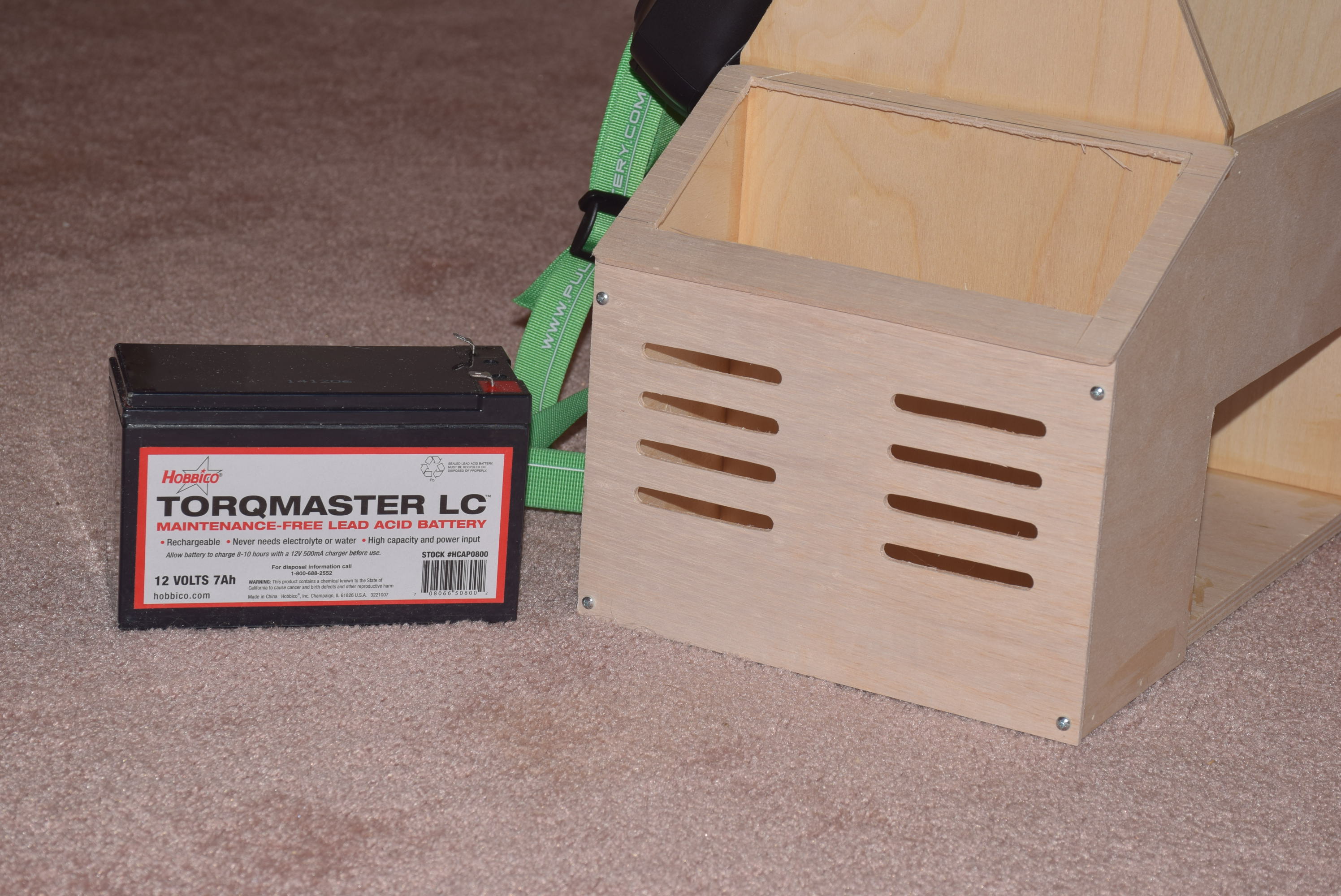
The Hobbico Field Box has been around for a number of years and includes some great equipment that compliments anyone with a nitro RC plane. When I purchased my first glow-fuel plane, I also purchased the Hobbico Ultra-Tote field box. It includes a number of necessary items; an electric starter and a glow plug wrench to name a couple. The kit also includes a nice 7Ah 12 volt lead acid battery for powering the included electric starter and wired glow driver.
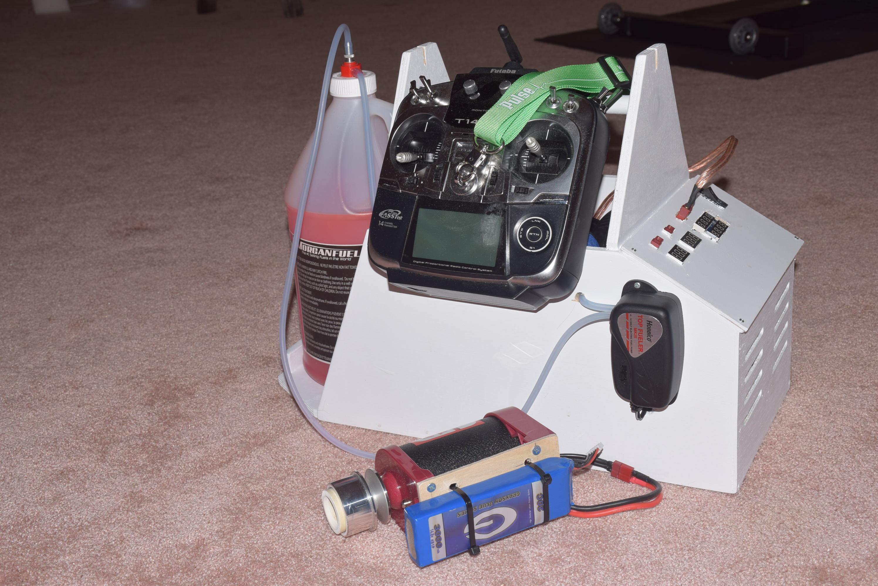
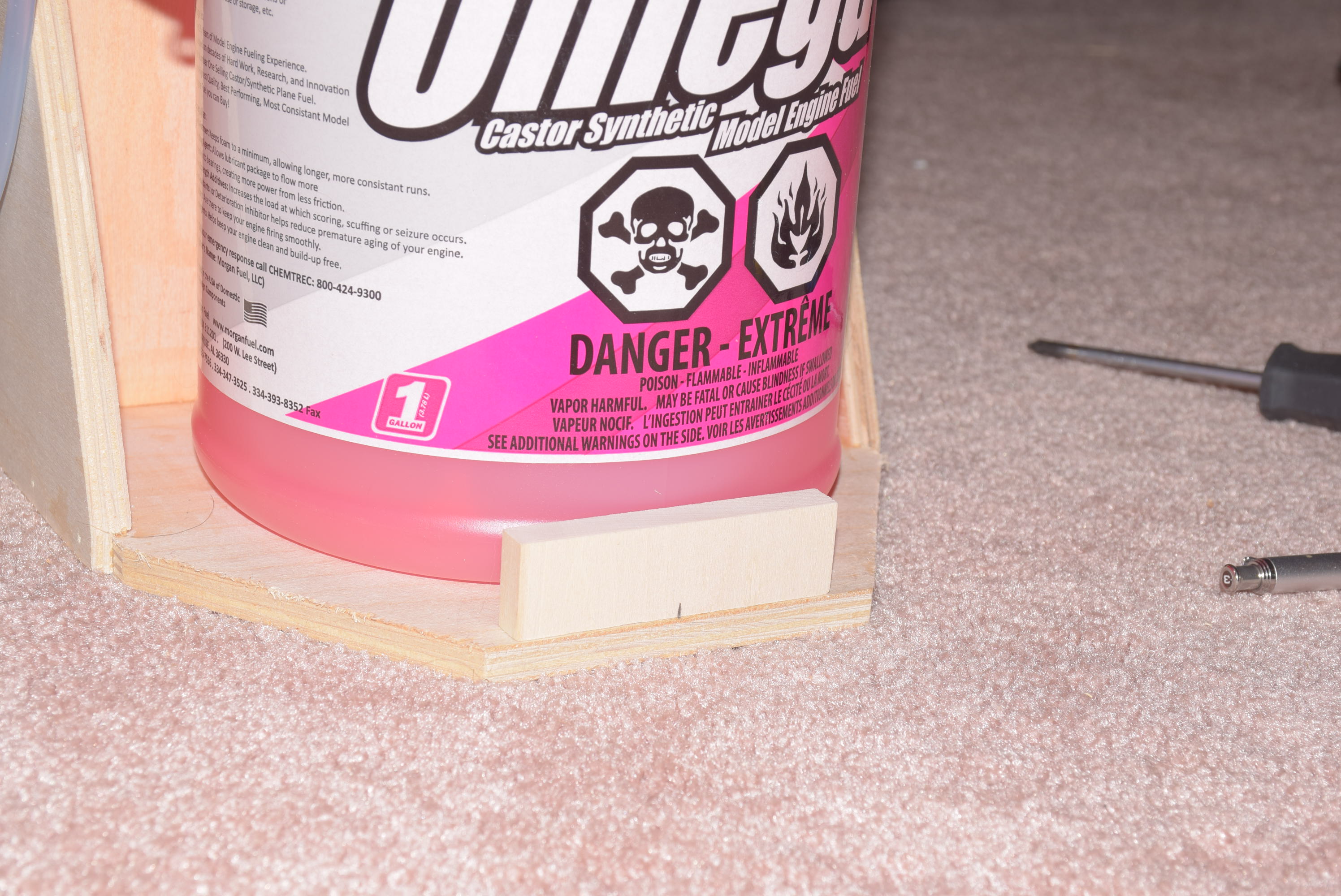
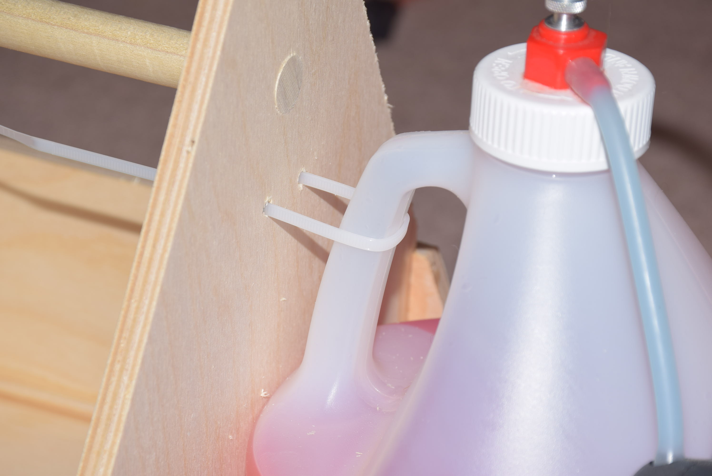
However, I decided I wanted to make a few modifications along the way! Once the basic box was built according to the manual I came up with a better way to secure a gallon of glow fuel in the caddy. I started by adding a one inch high by 3/8 inch thick piece of basswood that serves to keep the fuel jug from being able to slide out of it’s intended location. To hold this securely in place a simple zip tie was used to secure the handle of the jug near the top of the tote box. Using a zip tie in this location, helps to “wedge” the fuel jug in place preventing it from slipping or sliding around during transport.
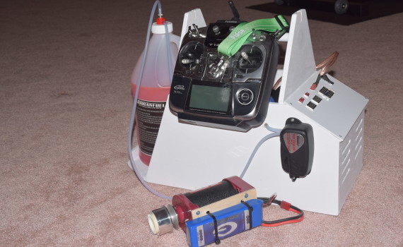
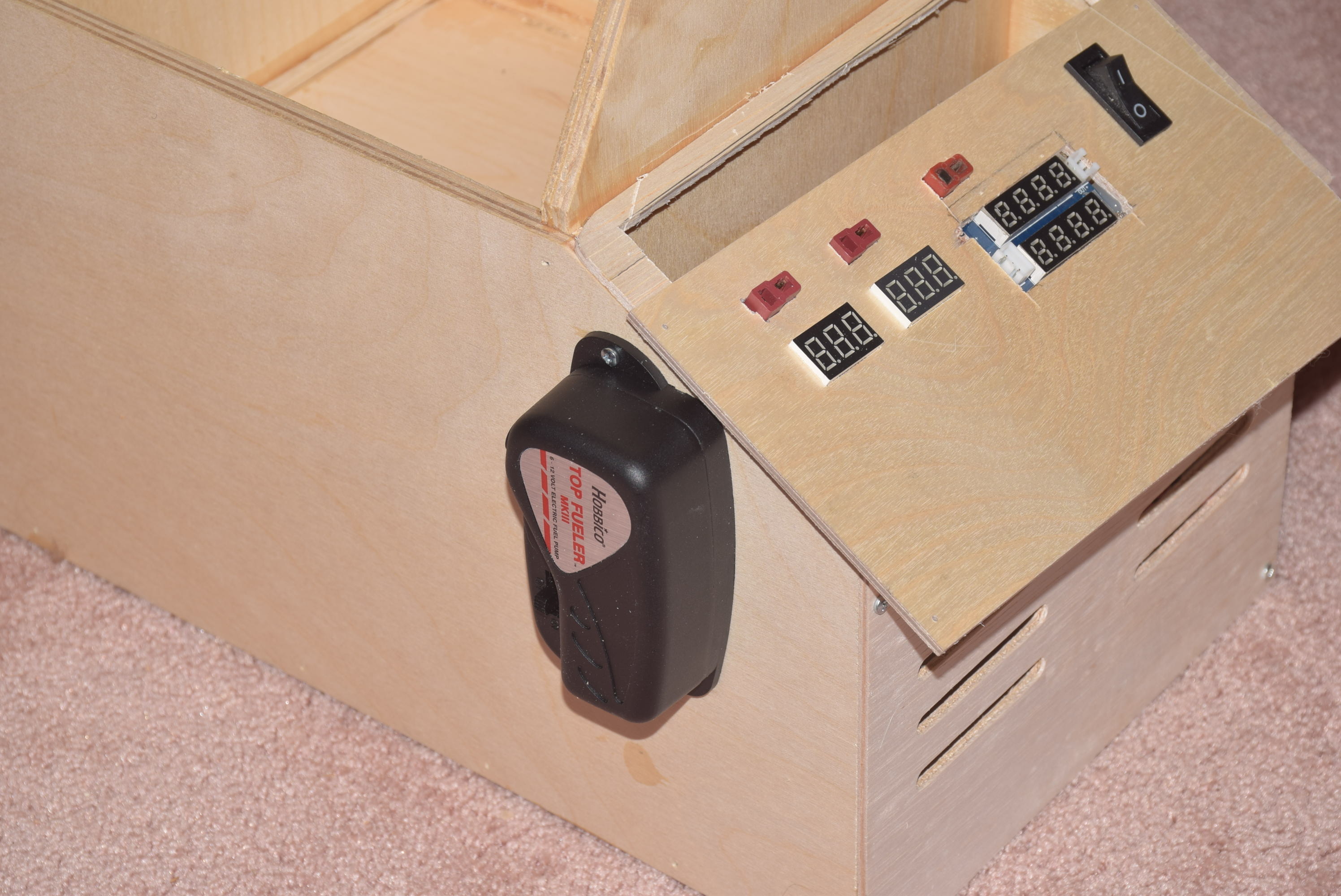
Next, I came up with my own design for a “power panel” of sorts. I added an “always hot” charge plug so I could charge the lead acid battery without having to remove it from the field box. I also added a couple of voltage meters, a current/amp display for the glow driver and a master switch that powers the entire panel. There are two main 12 volt power sources, one of which is tied to the master switch but the one on the far left is always hot – directly tied to the battery which can be used for charging or as a power source for an external charger at the feild!
I also installed a current limiting device that allows me to adjust the amount of current (amps) the glow driver is allowed to use. More amps equals a brighter glow. I set my current to be a little brighter than a standard 1 cell NiMh glow driver is able to deliver. I added a deans plug to the included wired glow driver so I could use this as needed and unplug it when I was done using it. I also added a two foot extension to the glow driver cord for a little more length. To wire everything together, I used a power distribution board. (Any distribution board suitable for a mini quad copter will suffice.)
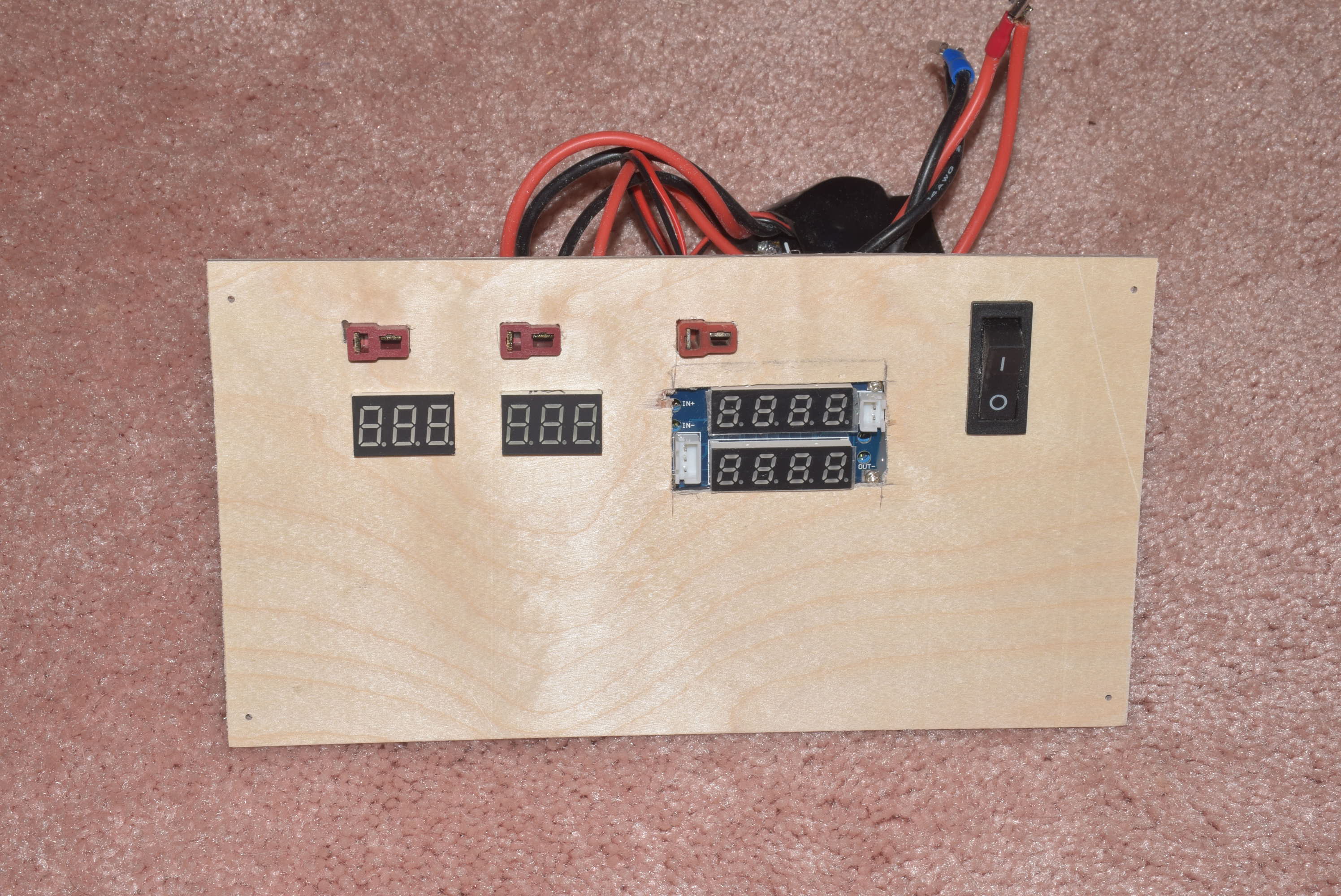
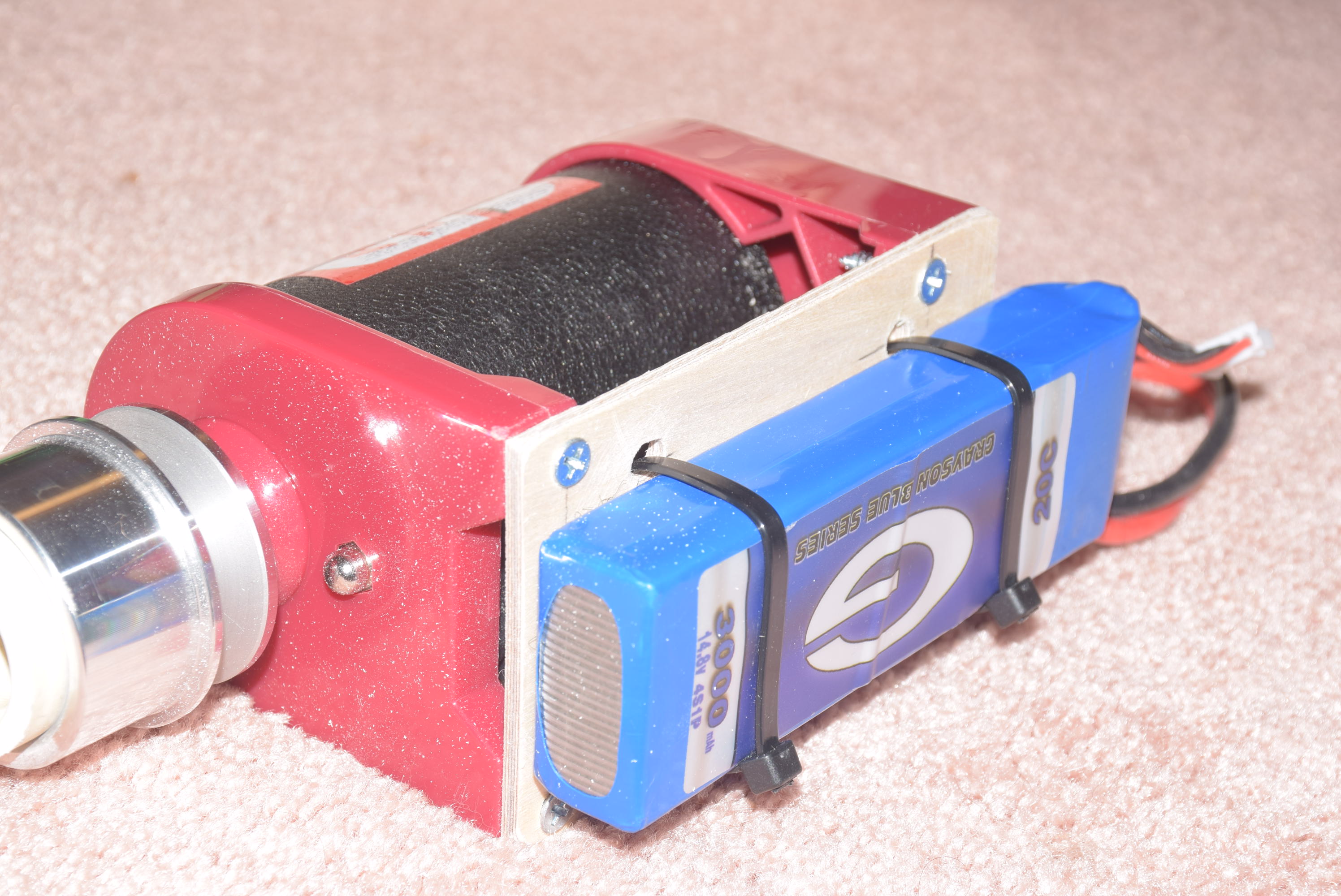
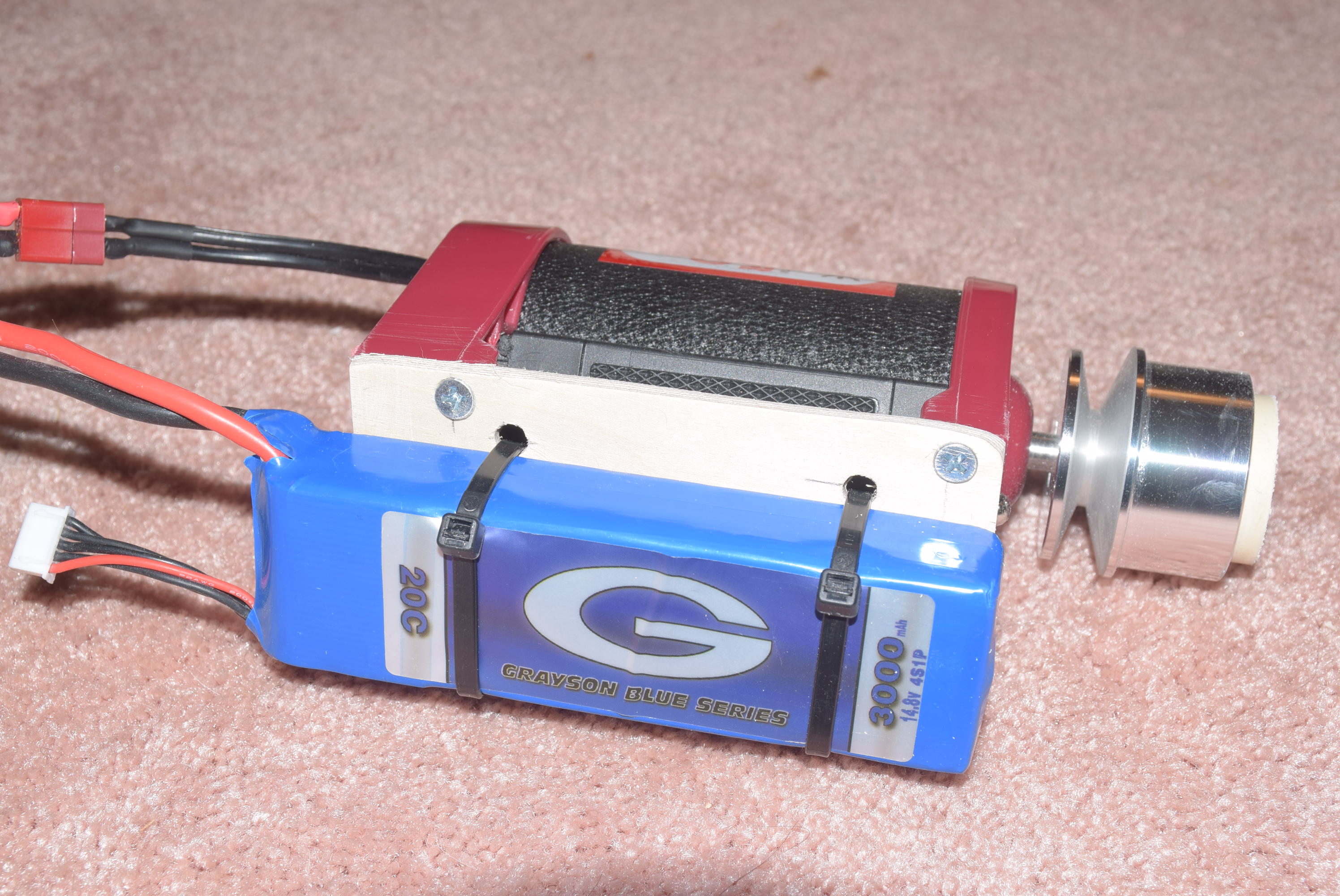
I also opted to mount a 4 cell (yes that’s right – a 4 cell) lipo to the included Hobbico starter. Going the “wireless” route here means you won’t have to worry about any power cords getting caught in the propeller. The 4 cells gives a little more power and RPM for the starter to use. The jury is still out on the long term effects of essentially overdriving the motor by a few volts. It usually just takes a blip or two of the switch before the motor is running.
Another modification I made along the way, was to add a screw to the carry handle, which will serve to hold the transmitter in a convenient location when starting the plane. This allows me “hands free” access to the transmitter while starting the plane so I can run up the throttle trim during startup.
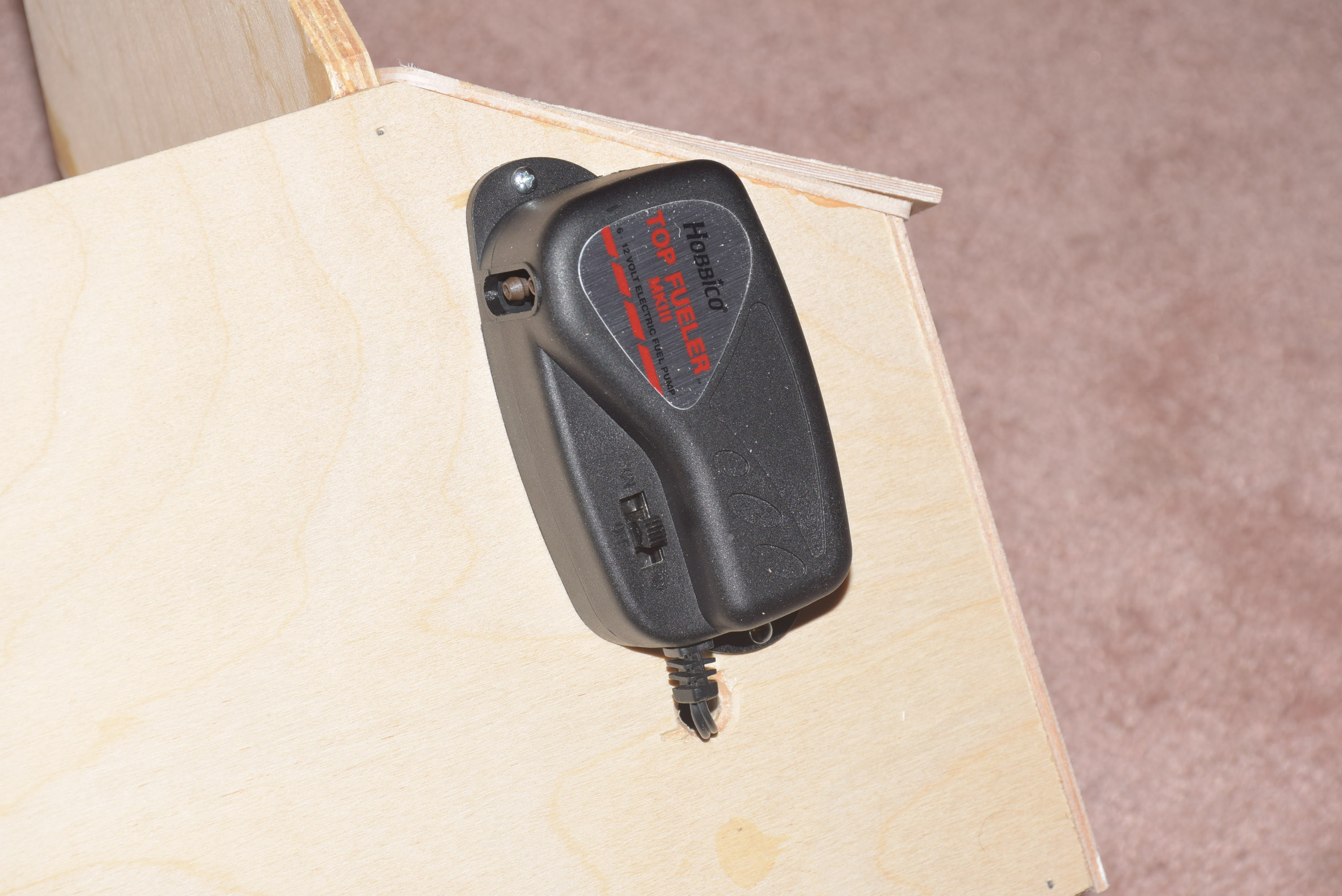
The ultra-tote also includes a nice electric pump in the kit. I mounted this on the side of the Ultra-Tote and used a servo extension to wire it to the power panel. If I ever need to replace the pump, I can just unplug it and wire up a new lead and plug it back into the power panel.
So far these modification have been working quite well and is making my plane fueling/starting procedures much more convenient! Much of the fun with this hobby is making things work they way YOU want them to! I’ve included a gallery of photos below.
Until next time, happy flying and RC’ing!
-
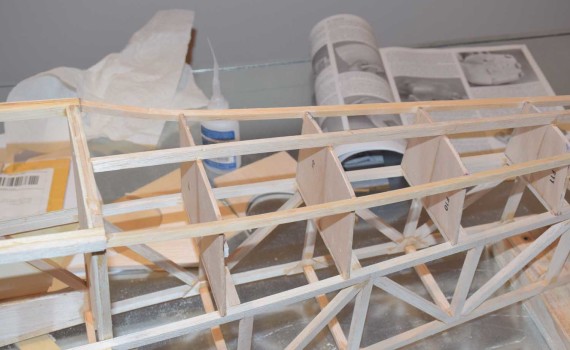
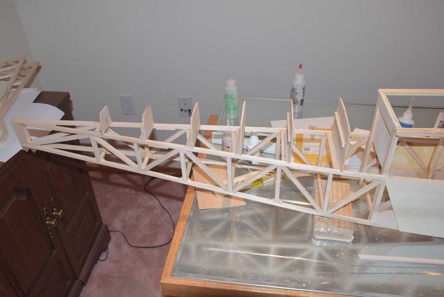
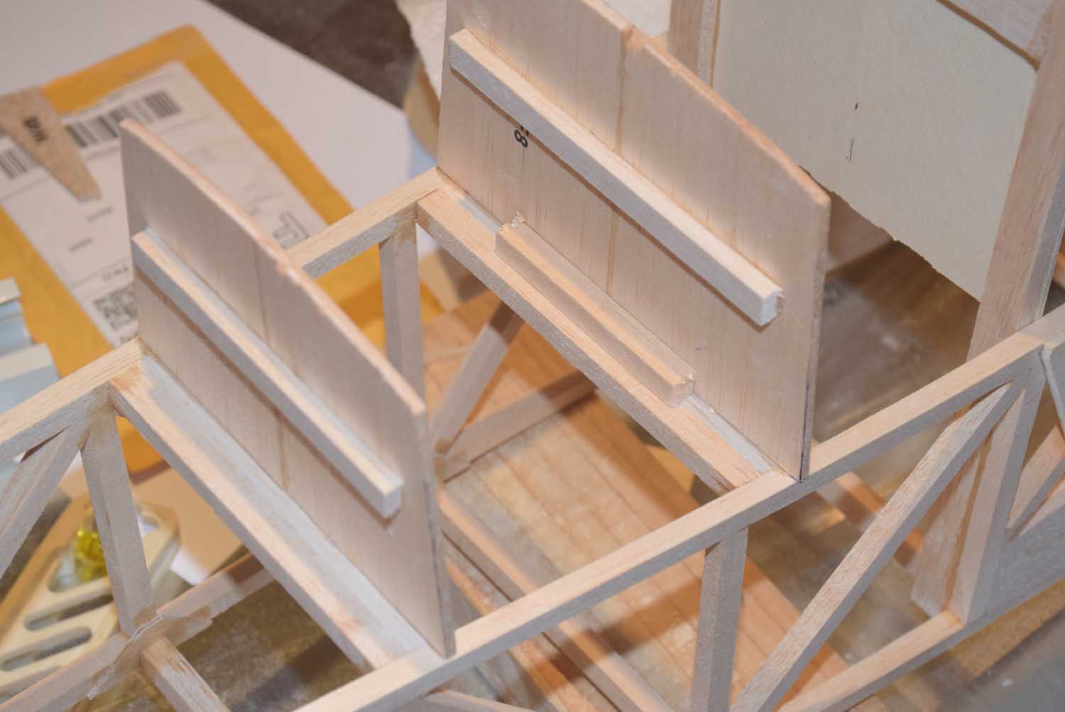
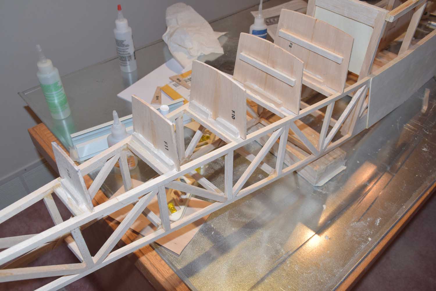
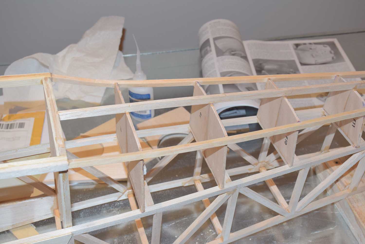
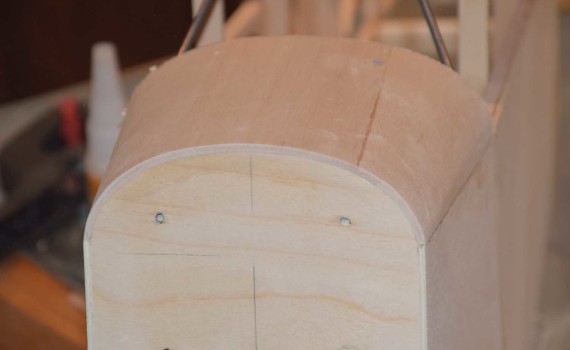
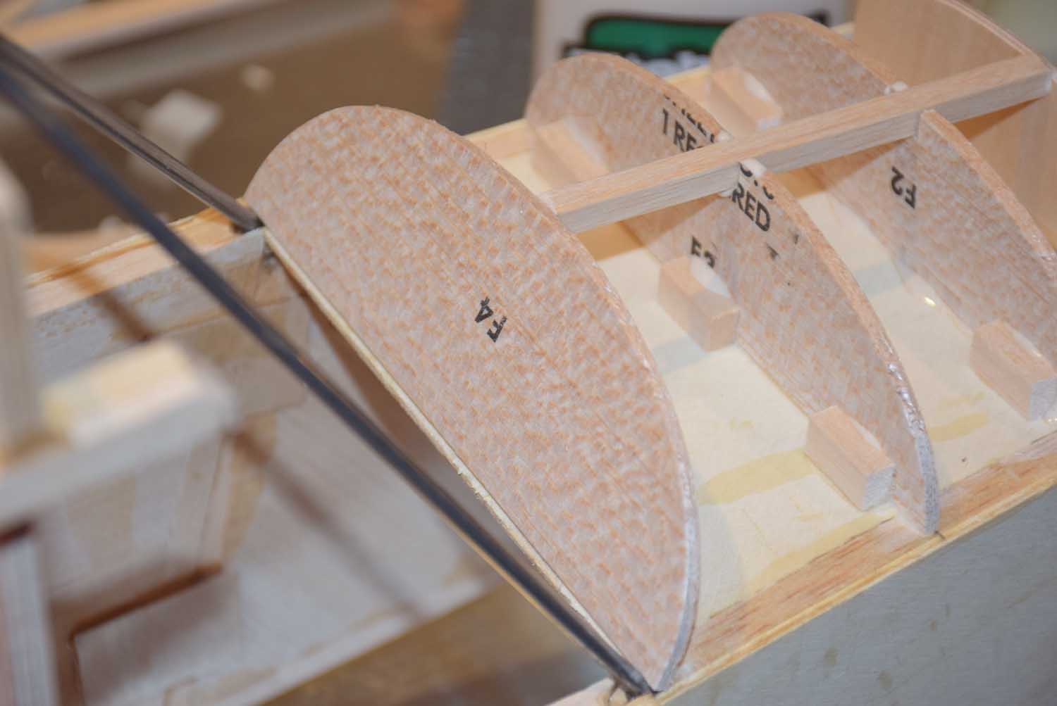
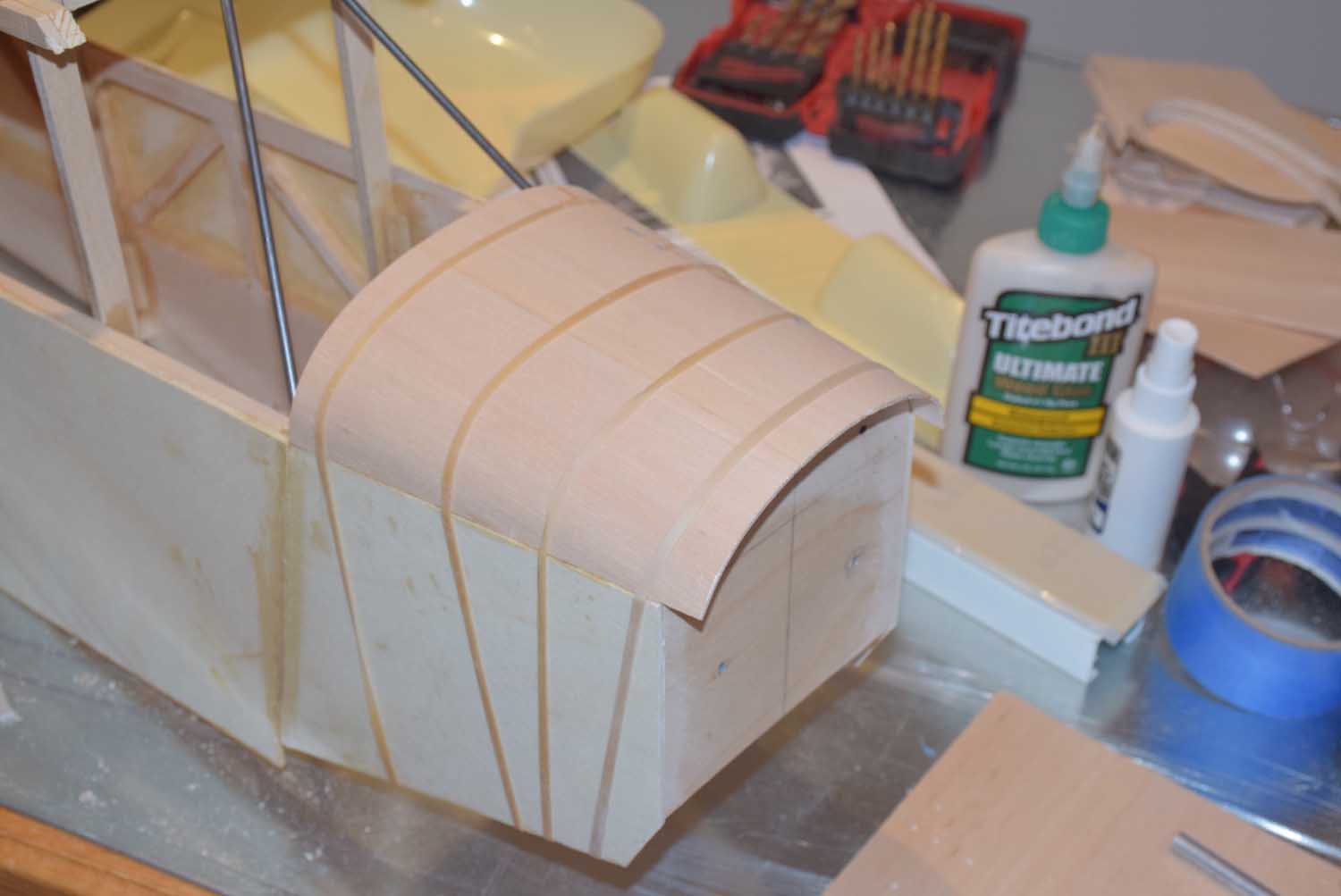
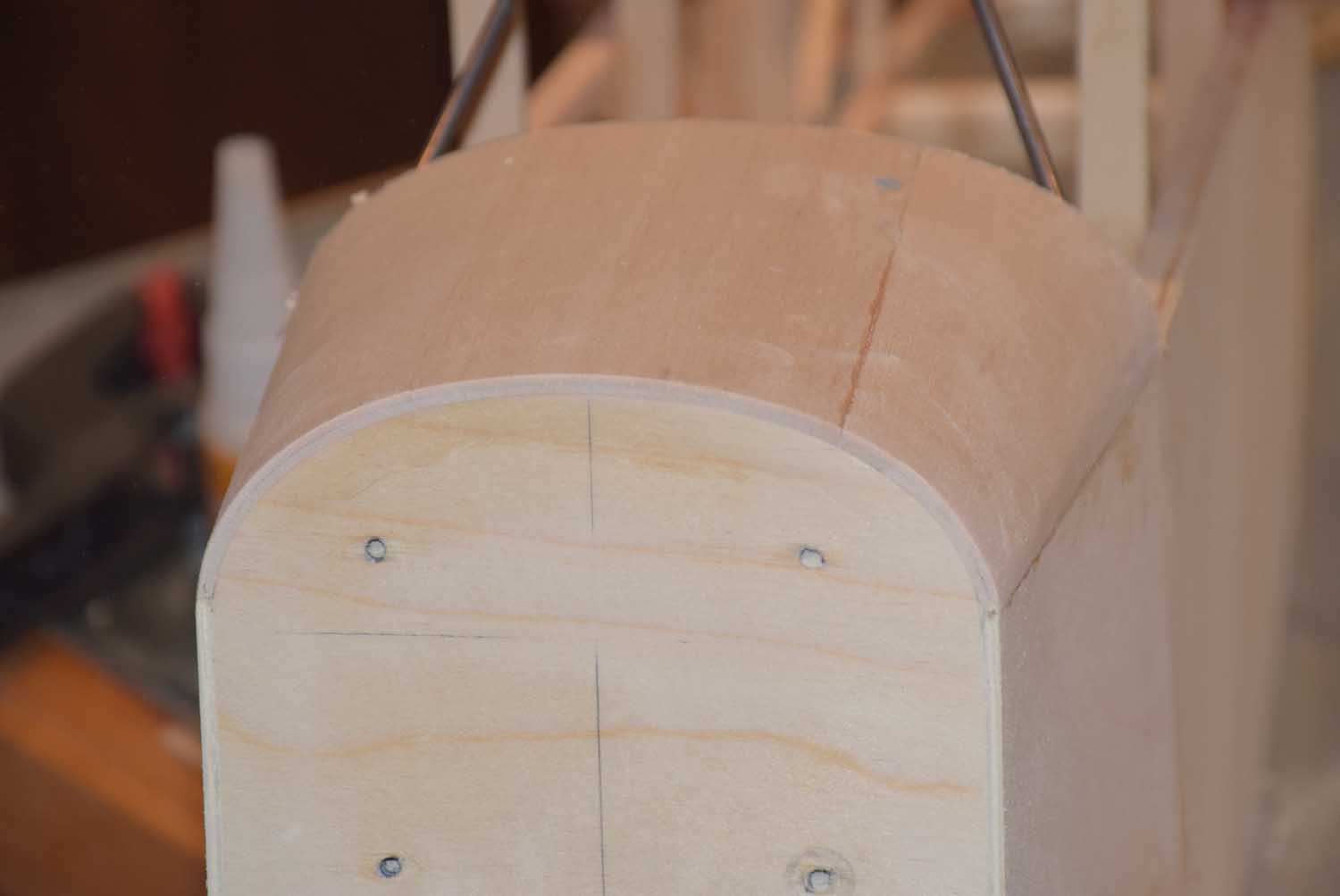
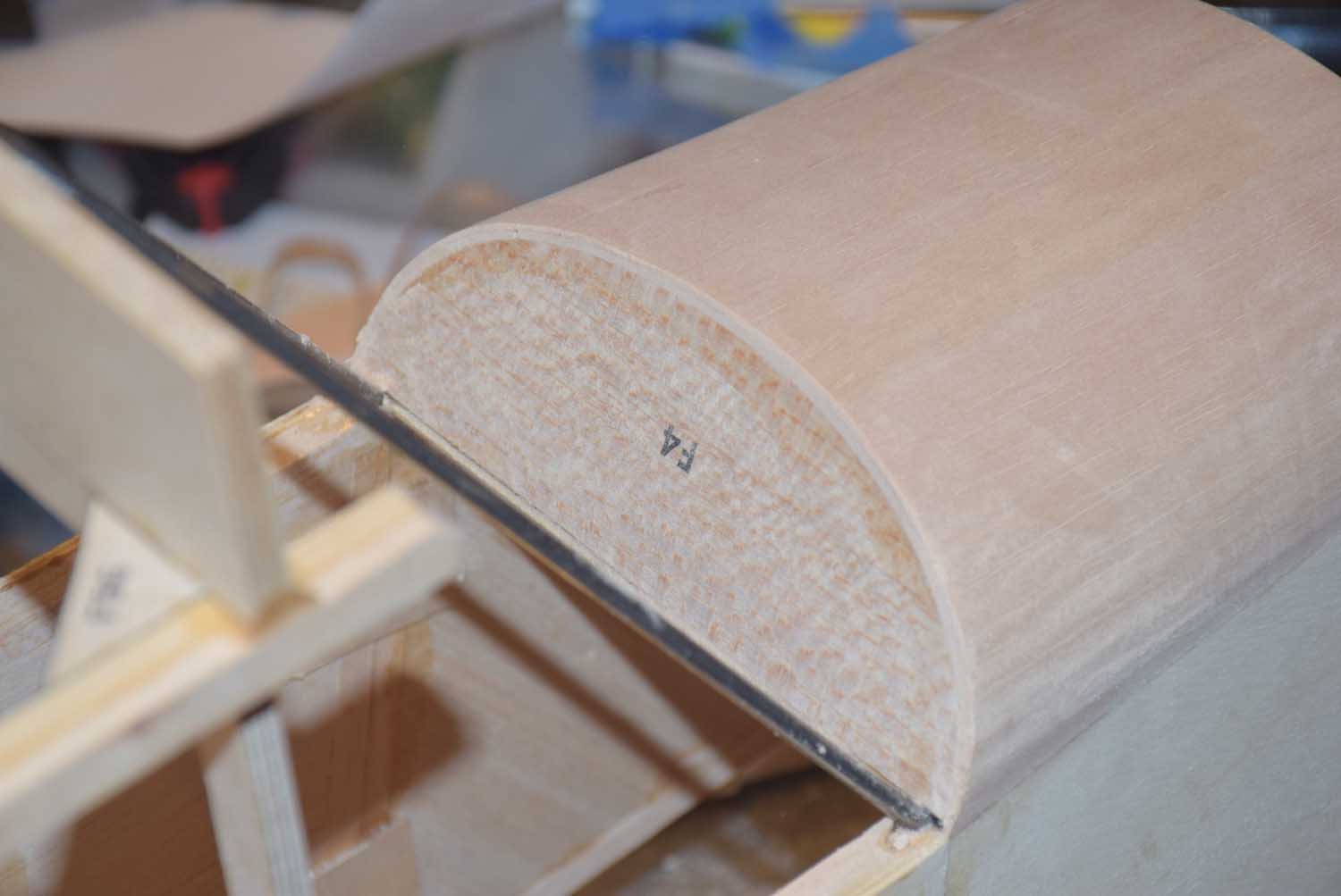
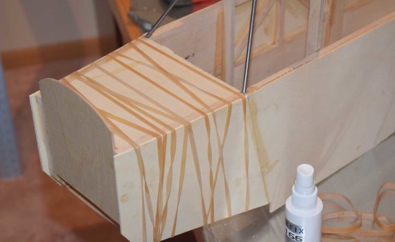
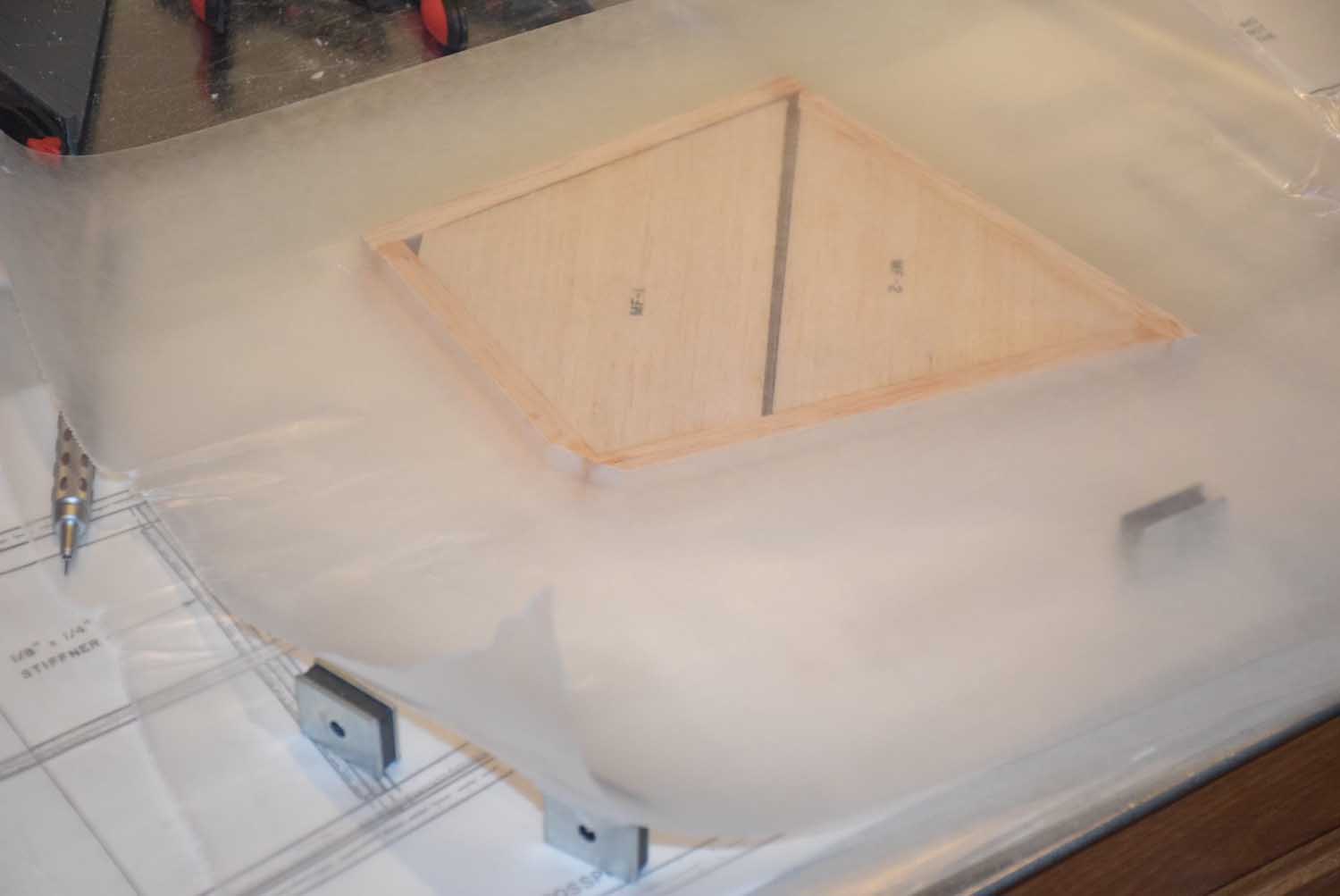
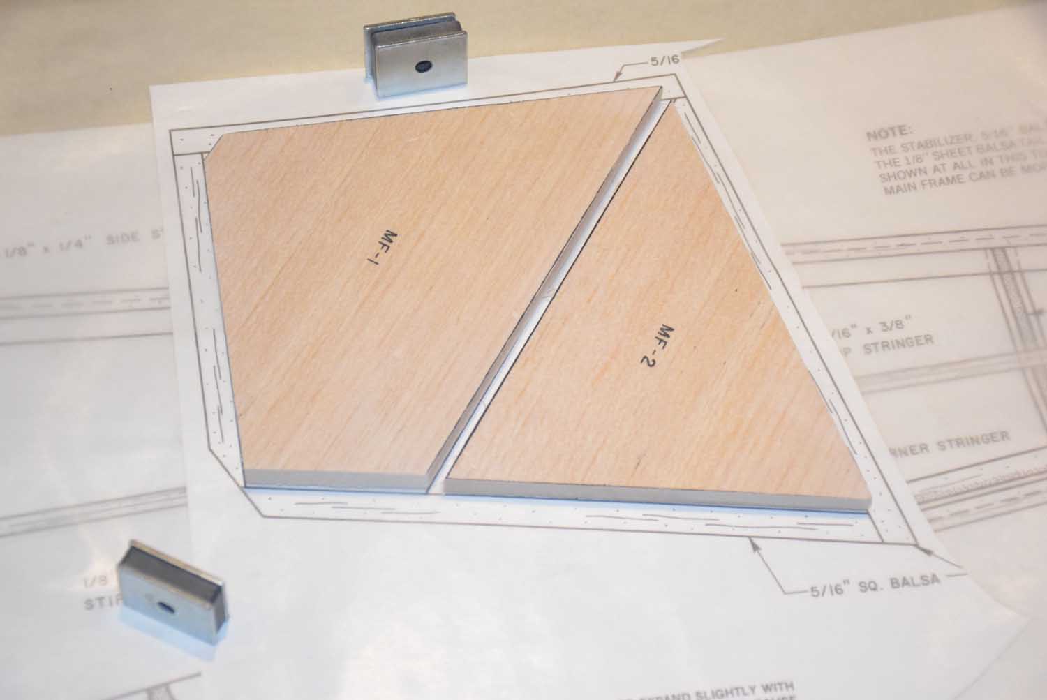
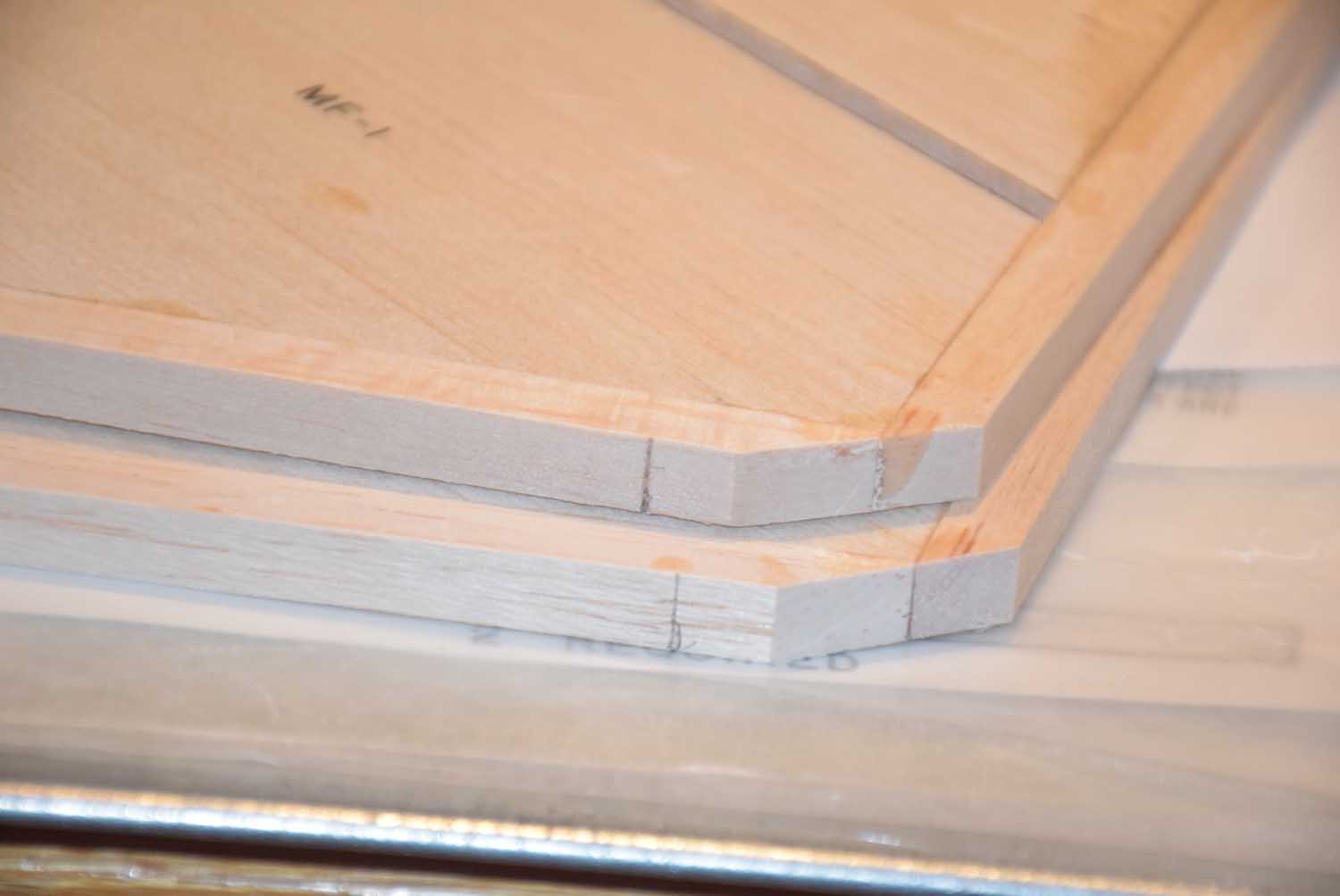
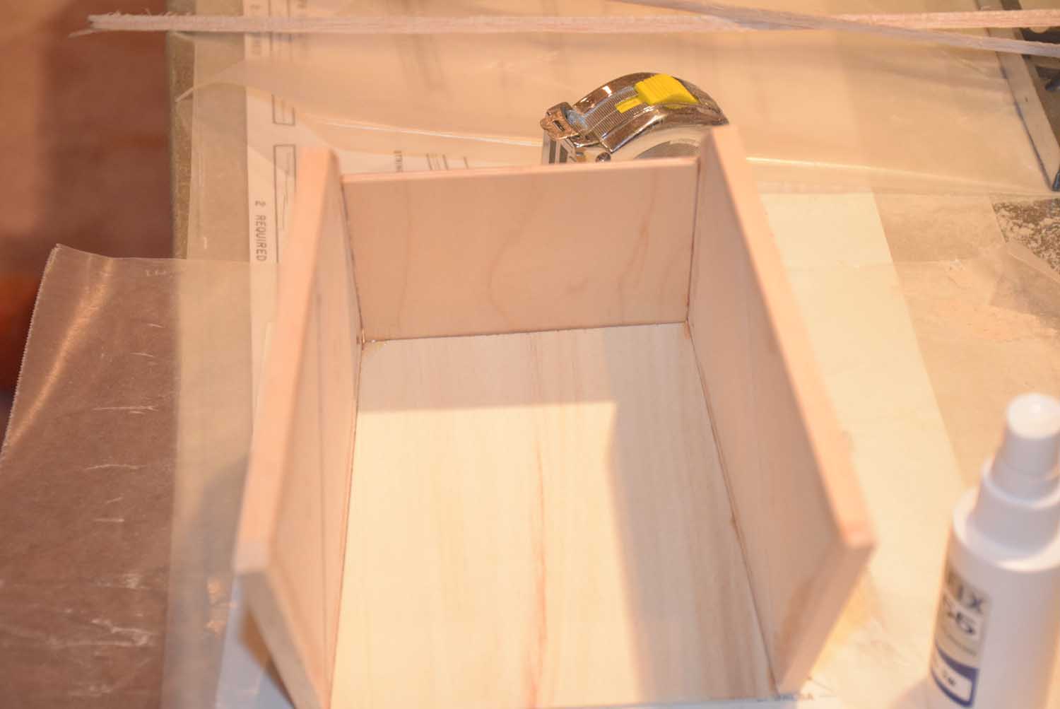
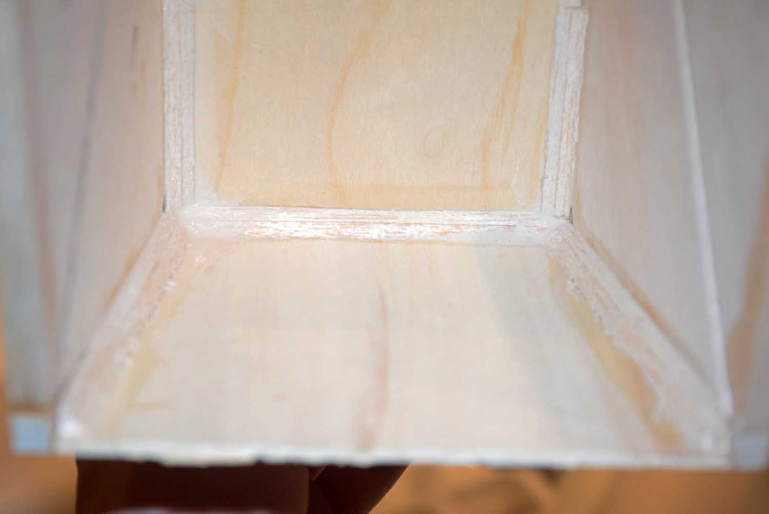
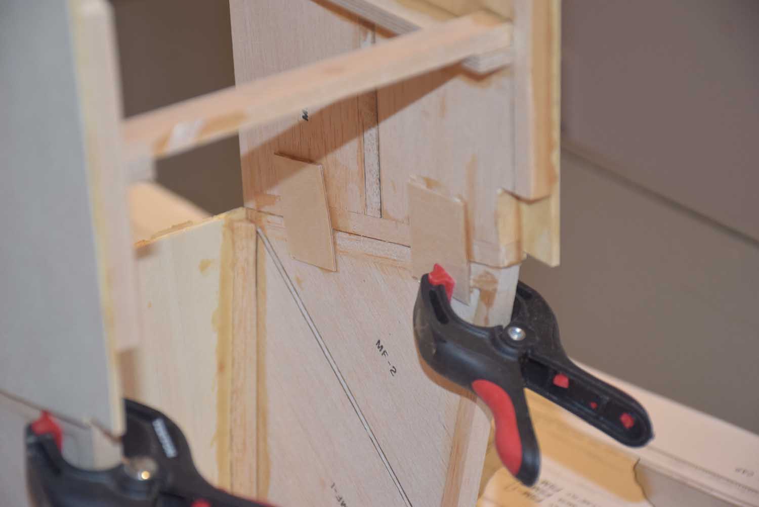
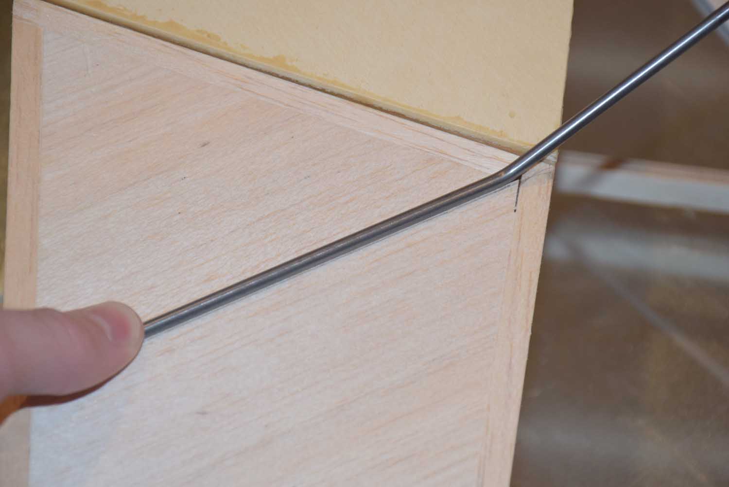
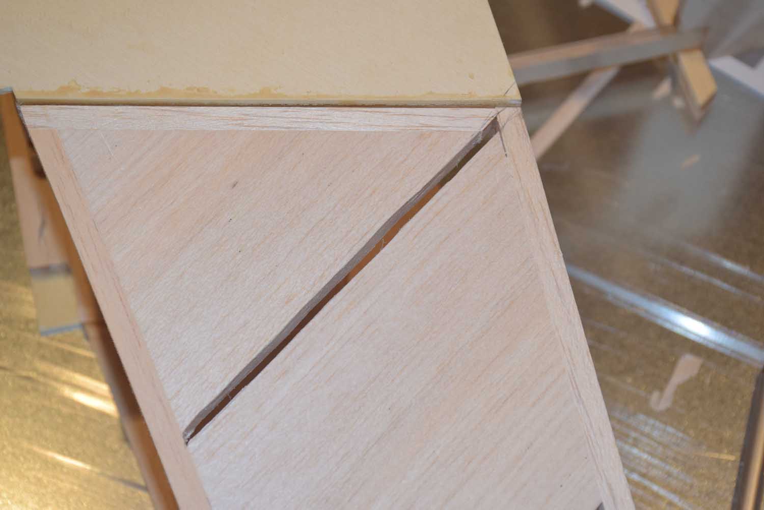
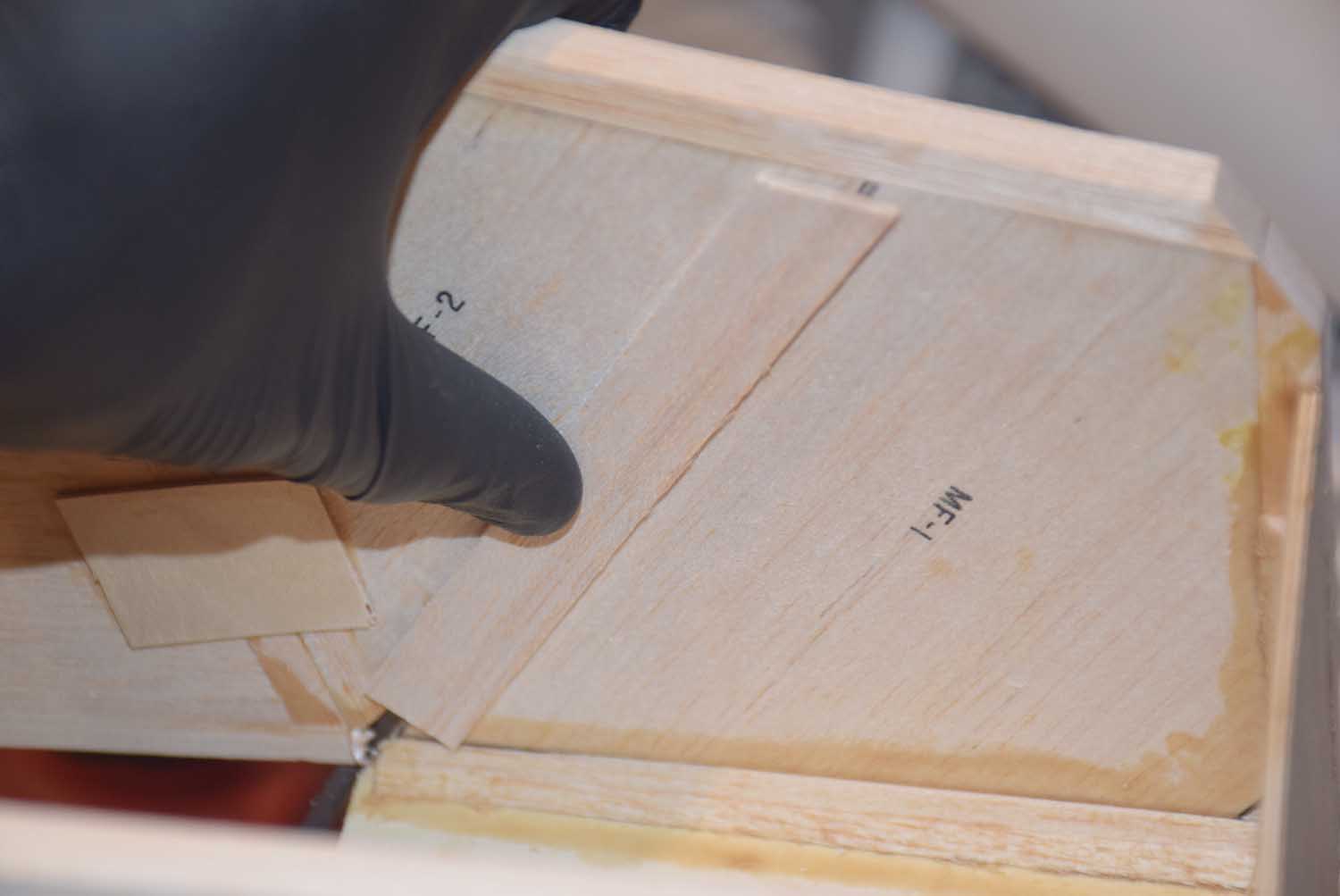
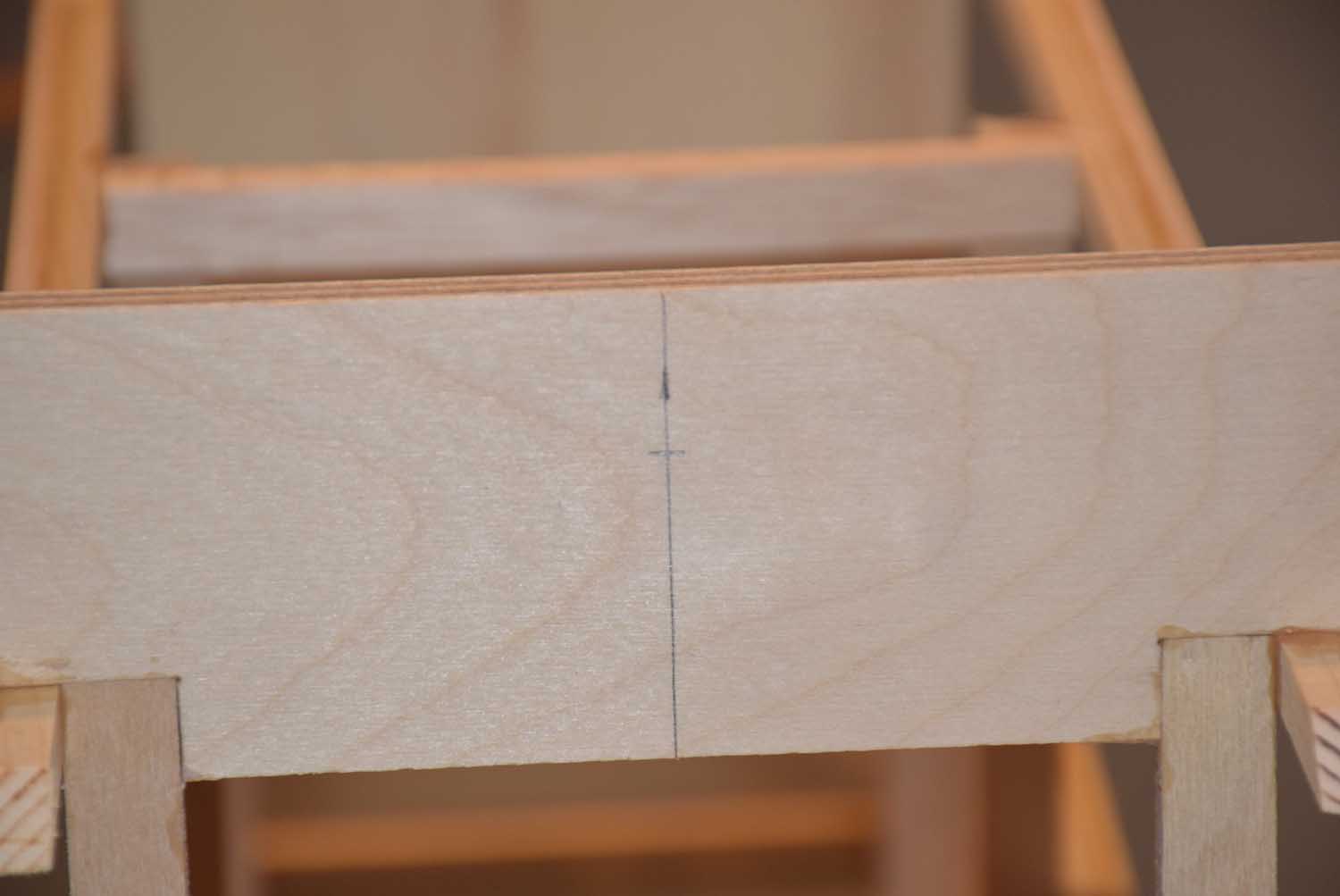
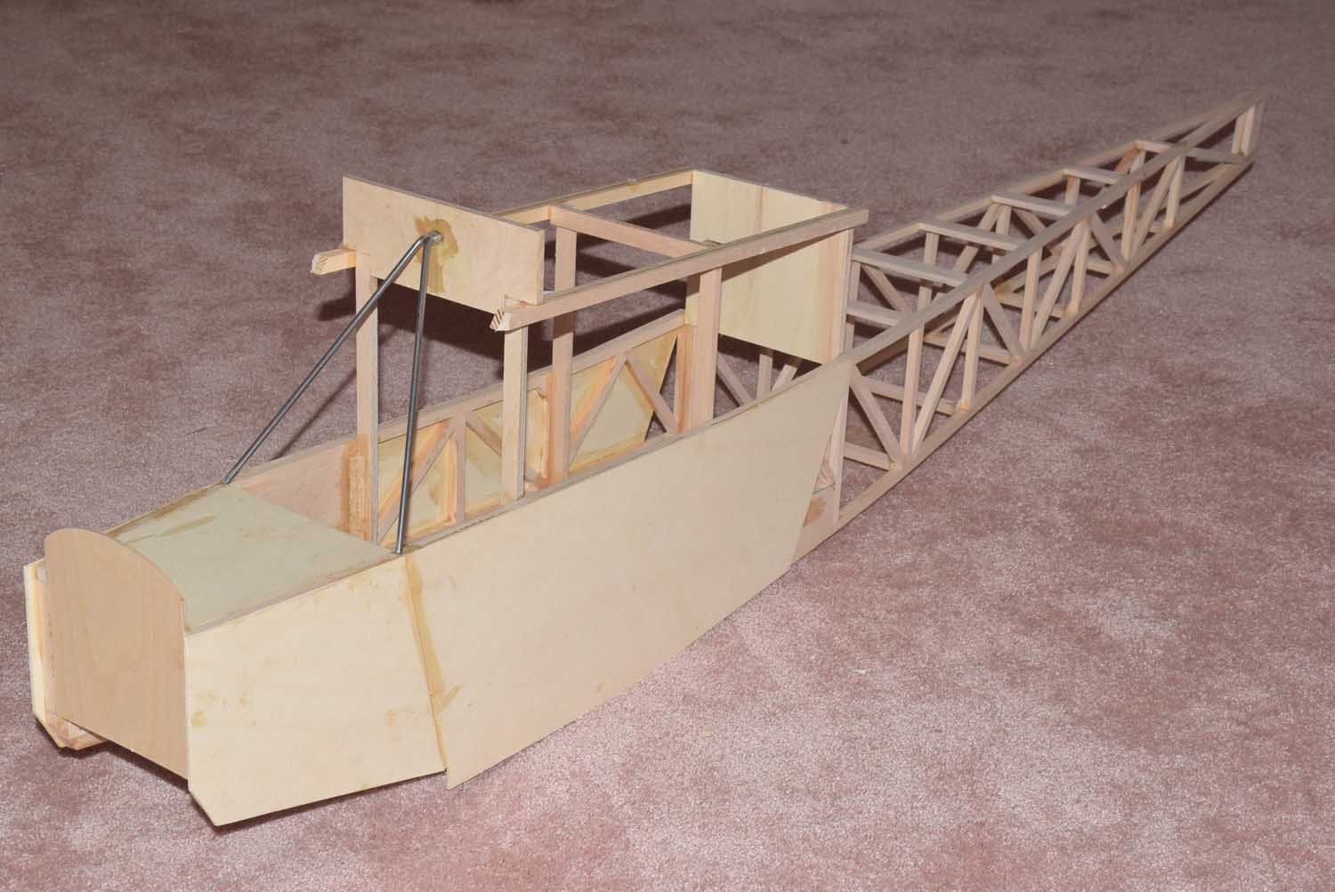
- Fieldbox before paint
-
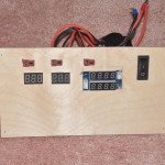
- “modern” power panel
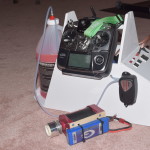
-
- 4s Lipo Hobbico Starter
-
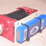
- 4s Lipo Hobbico Starter
-
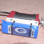
- 4s Lipo Hobbico Starter
-
- Electric Glow Fuel Pump
-
- Electric Glow Fuel Pump
-
- Electric Glow Fuel Pump servo lead.
-
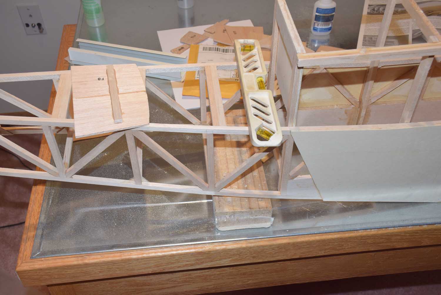
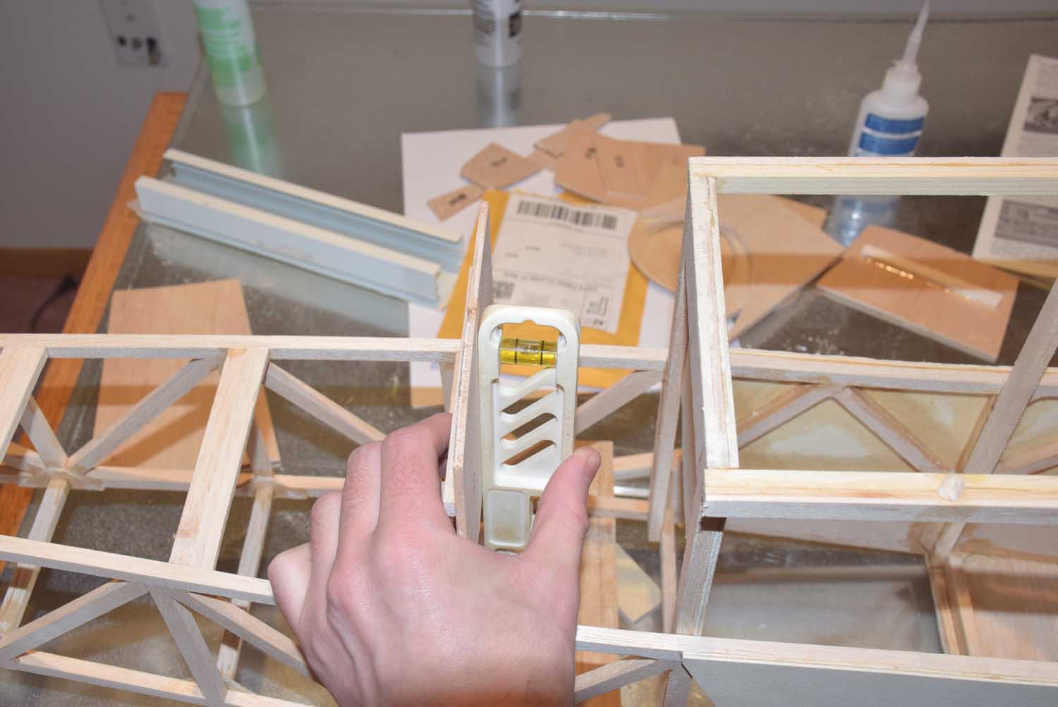
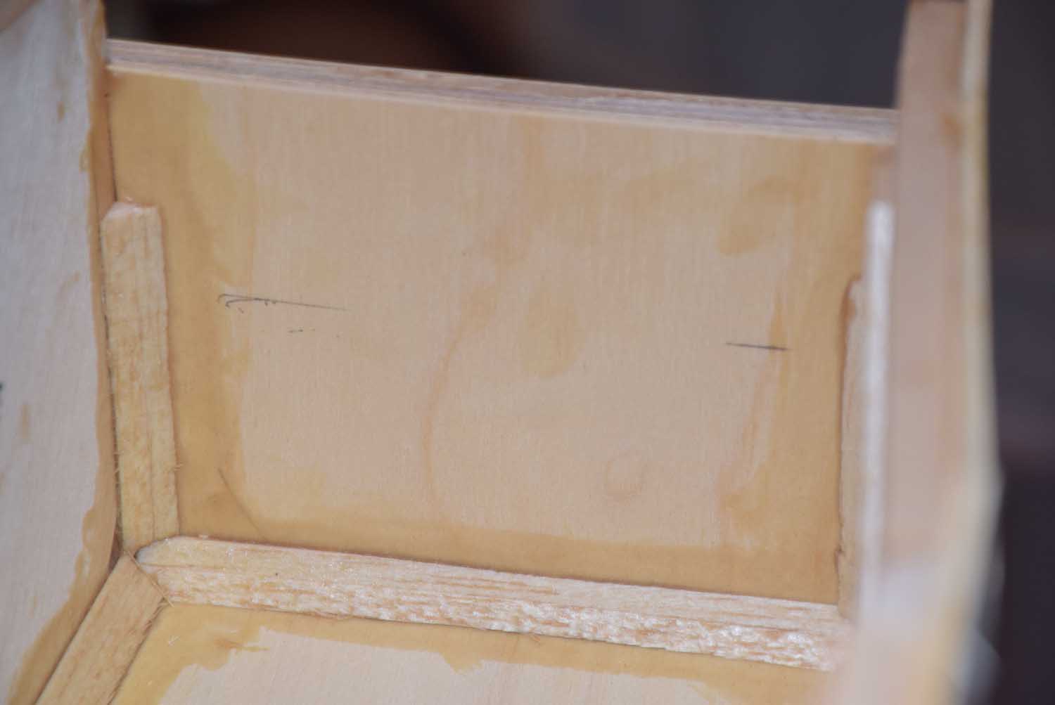
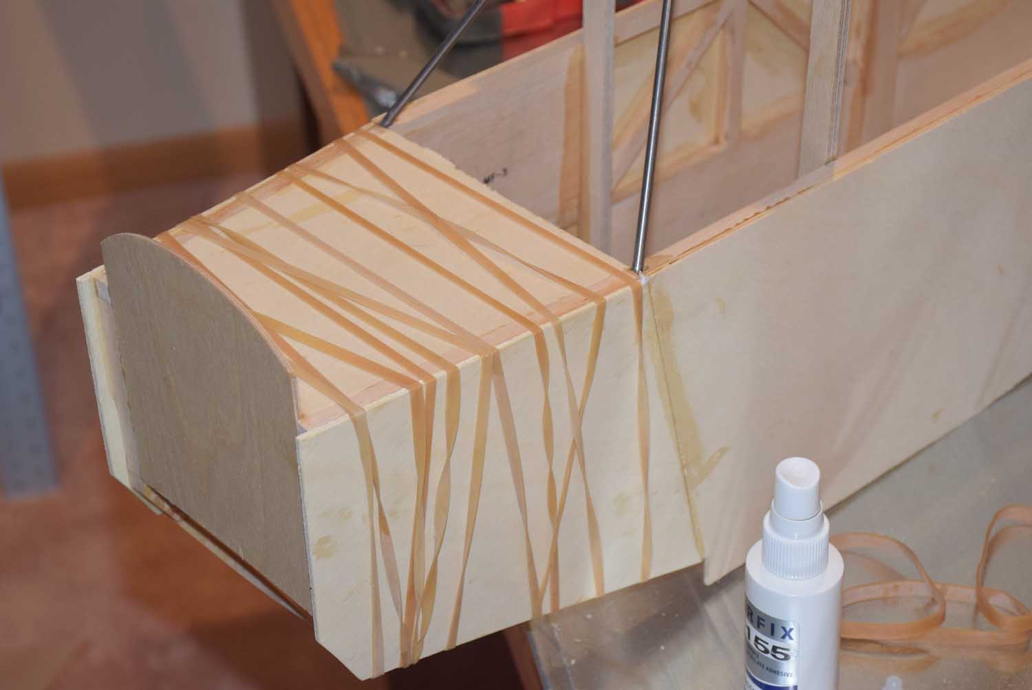
- Gluing in block for fuel jug restraint
-
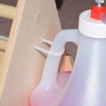
- zip tie holds the jug tightly in the caddy
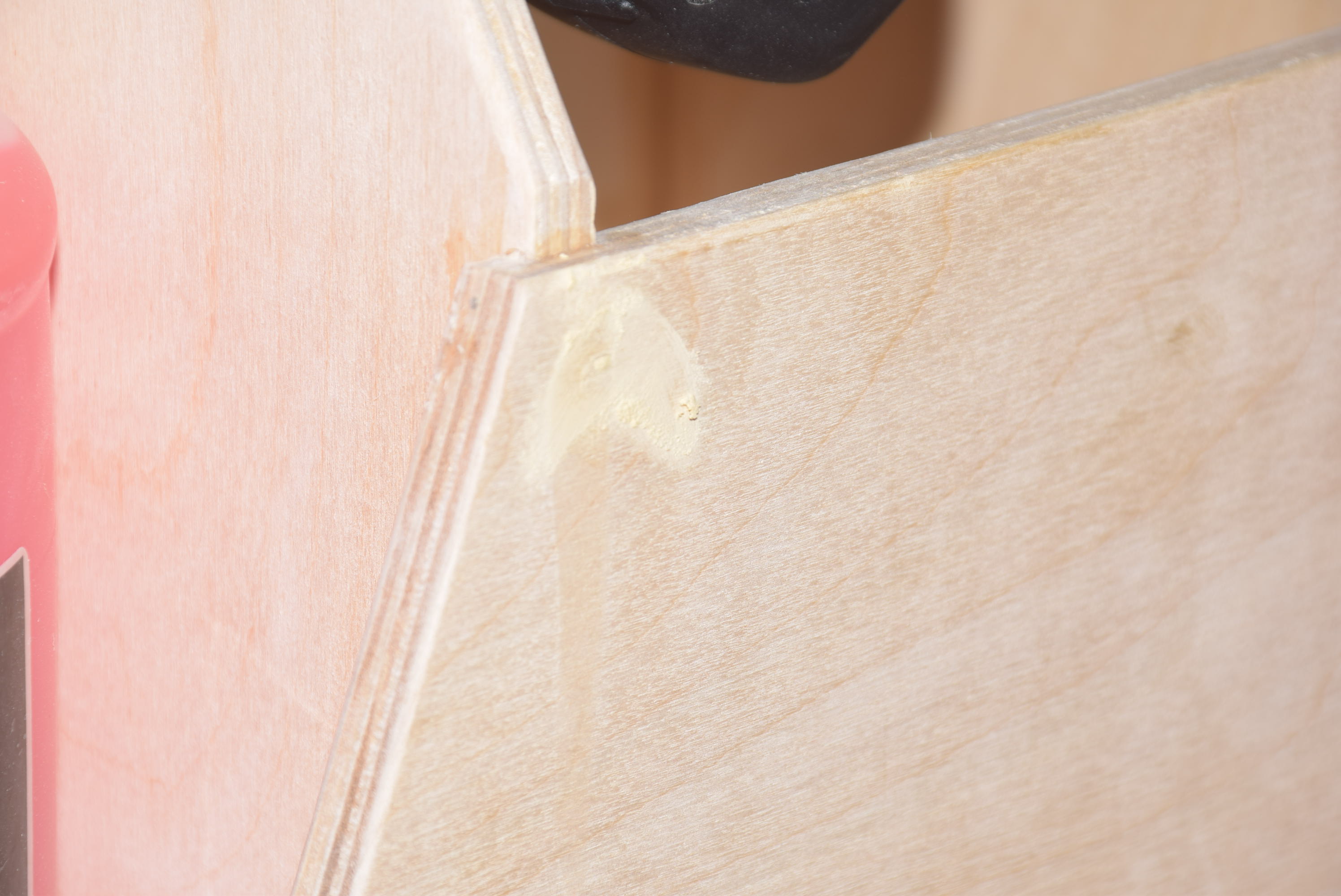
-
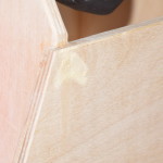
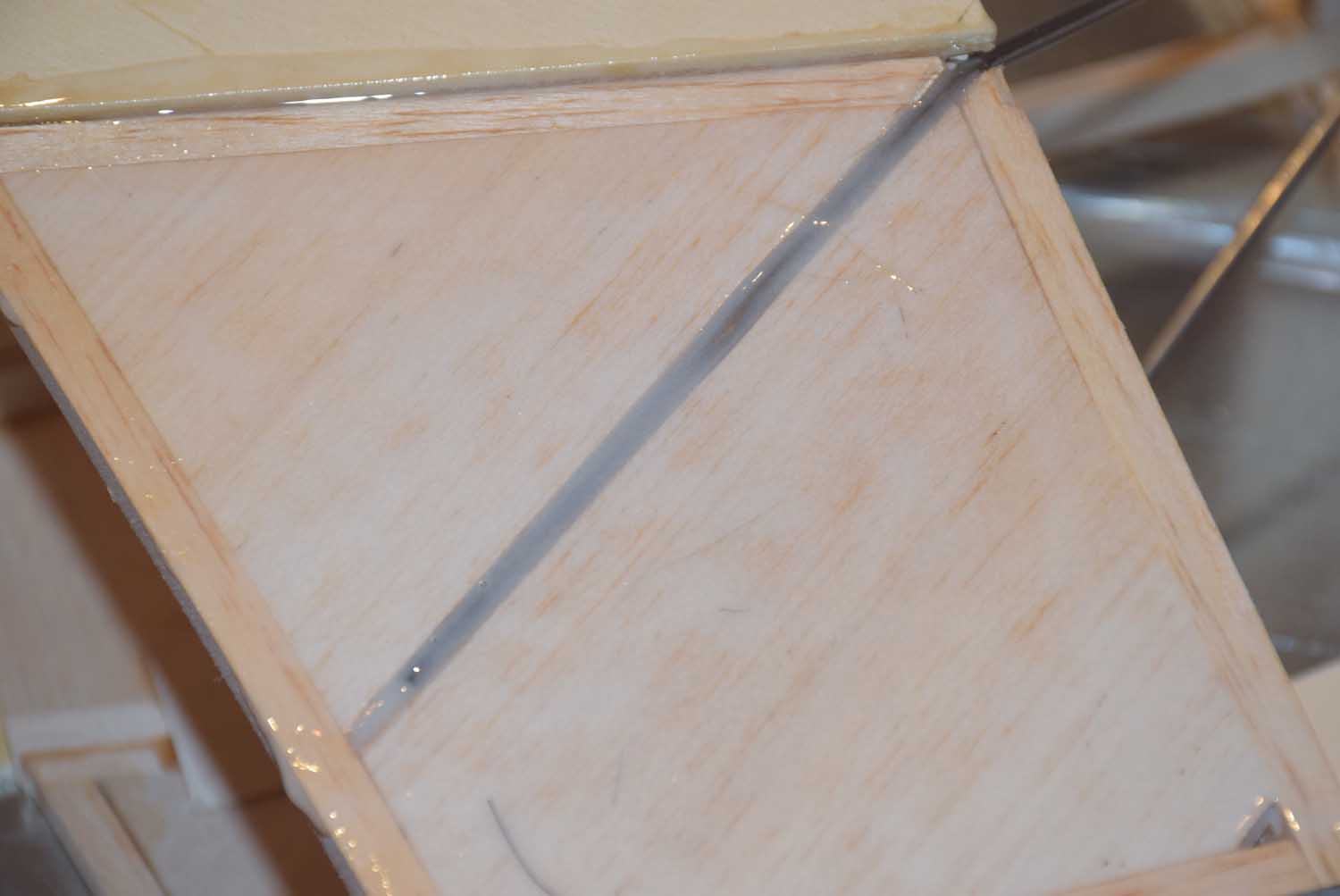
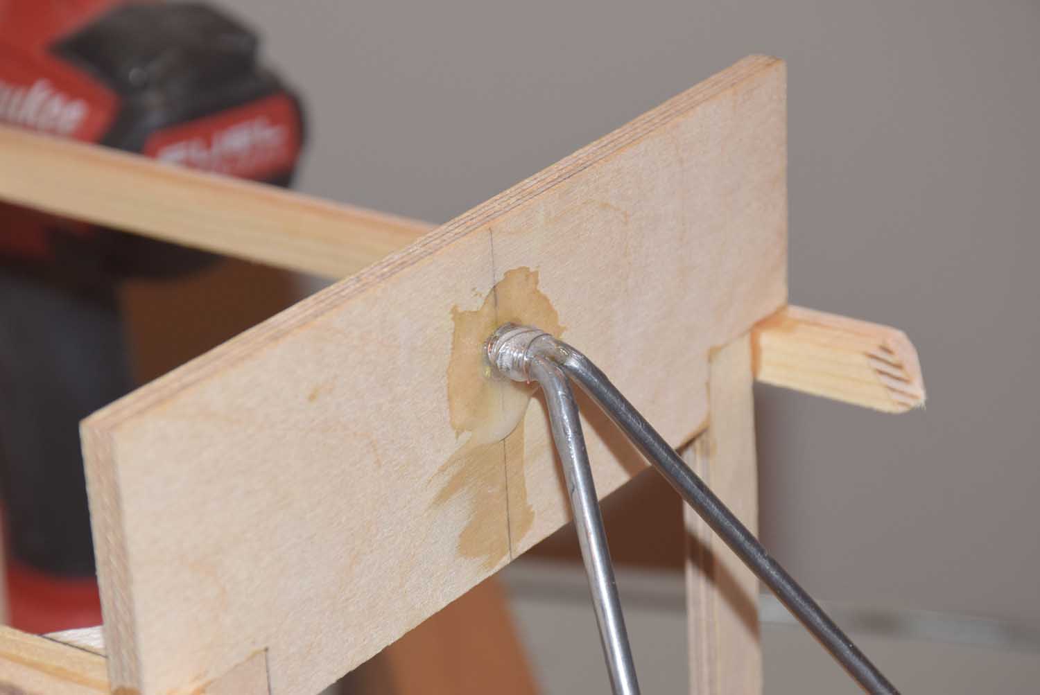
- filling in any nail holes
-
- All done and painted!