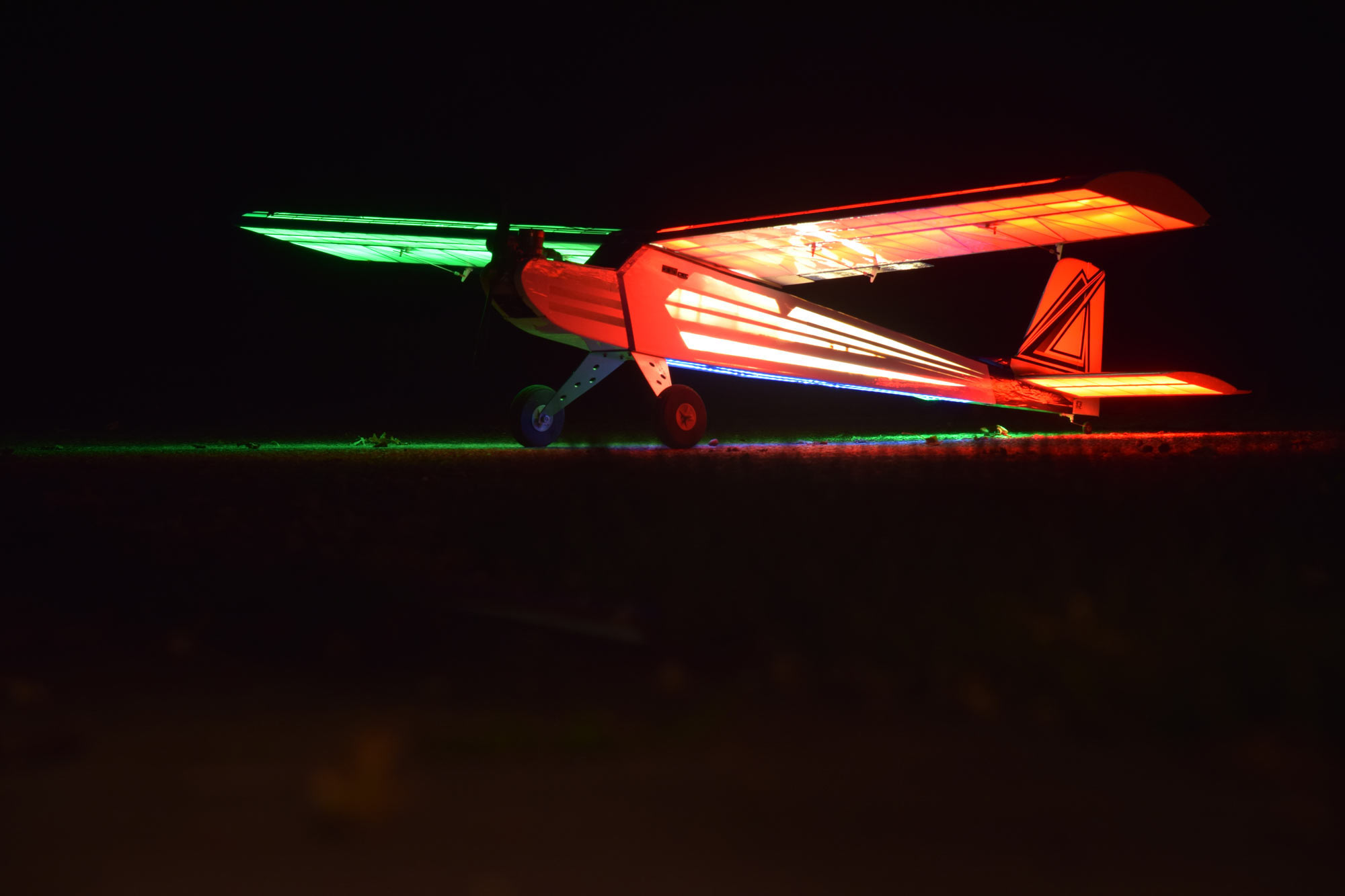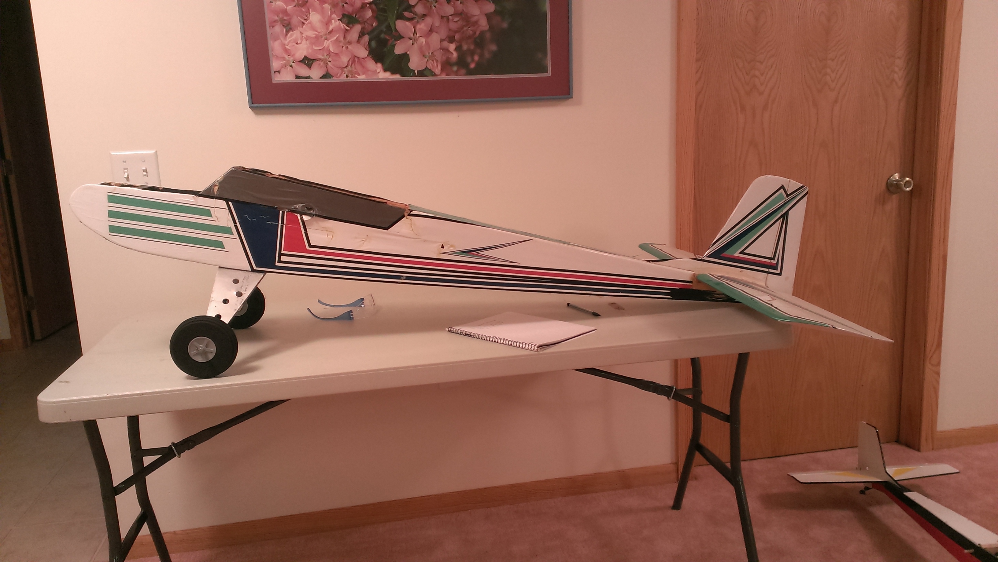
Sig J-3 1/4 Scale Cub Build Series – Part 4 – Truss work Fuselage Sides & Gluing Up Formers to Frame
Category : Model Airplane Building
Part 4 – Truss work Fuselage Sides & Gluing Up Formers to Frame
This is where things really start come together as they say!
In part 4 of the J-3 Cub Quarter Scale build series we will look at framing up the truss work fuselage sides and also joining them to the formers we built in part 1.
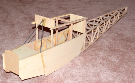
Building the fuselage sides for this model J-3 Cub utilizes truss work style construction techniques. Truss work framing is one of the strongest ways to build a frame but still maintain a very light weight frame. Truss work construction has a high strength to weight ratio.
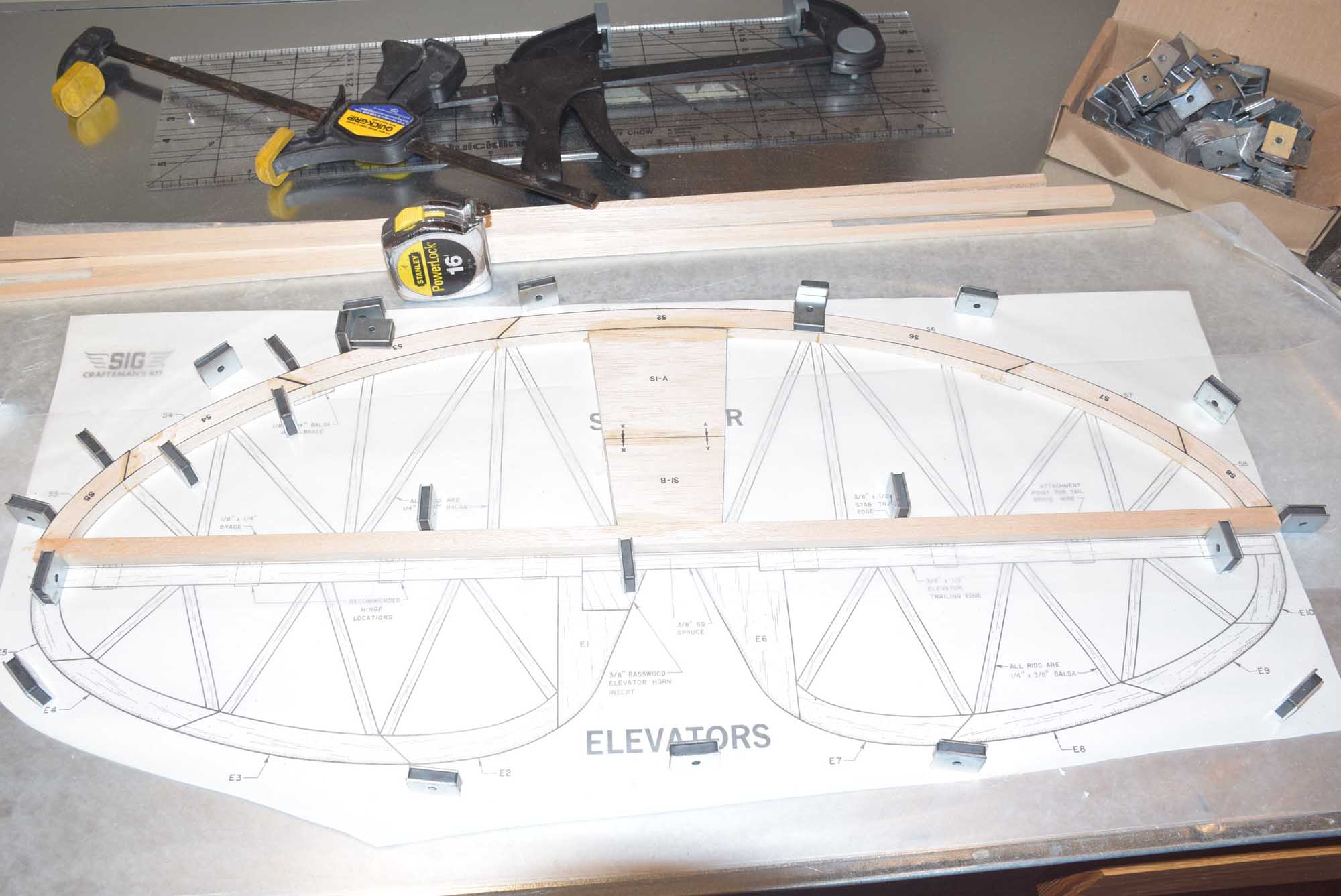
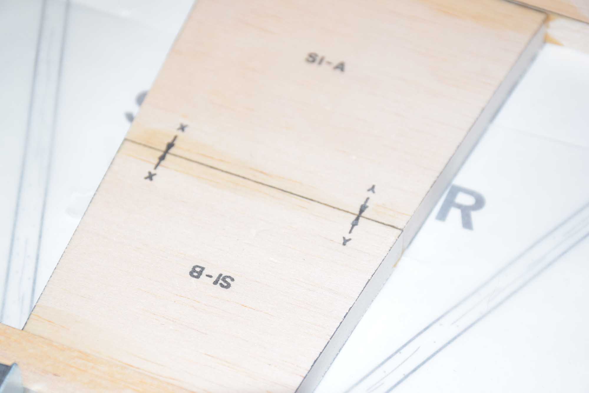
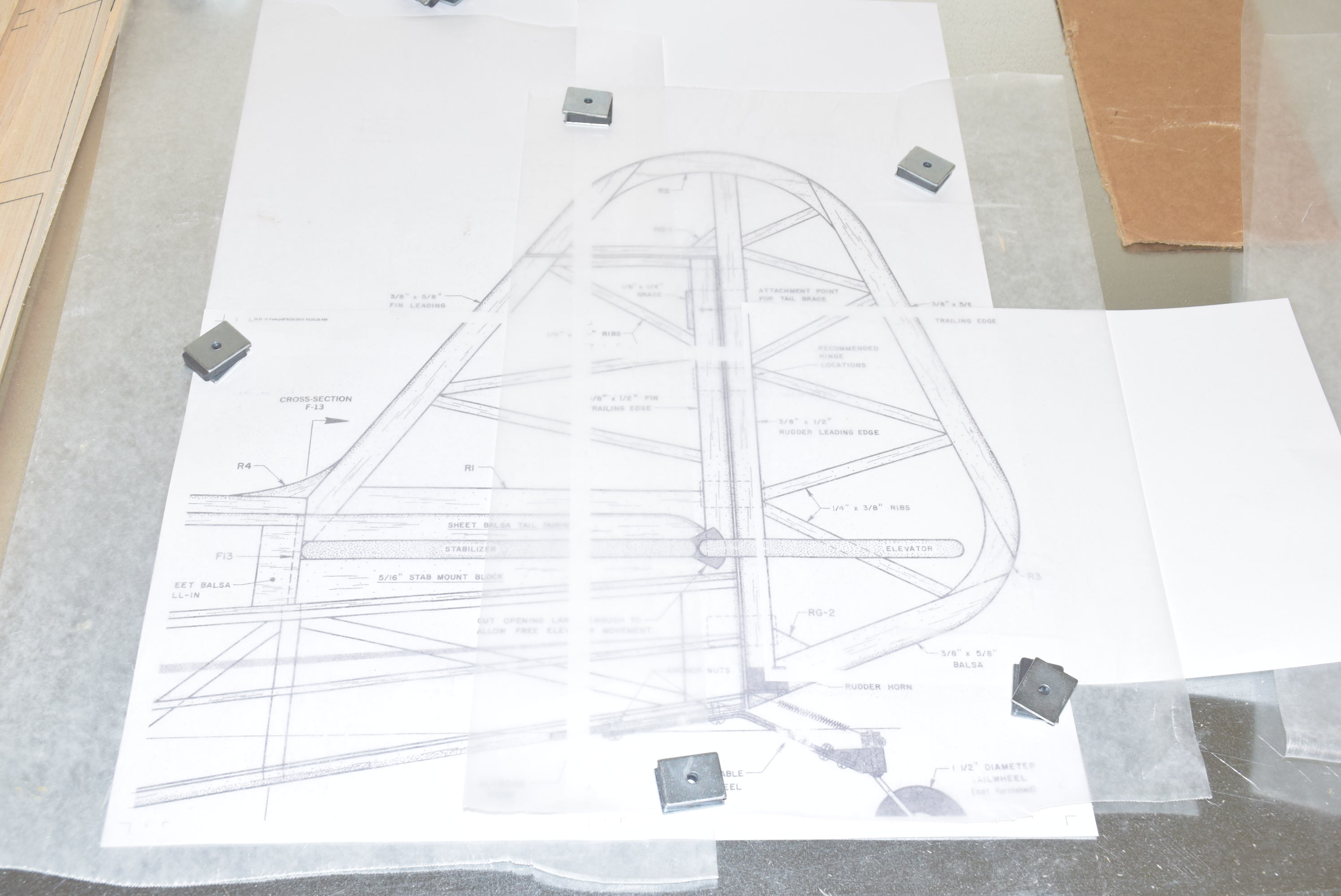
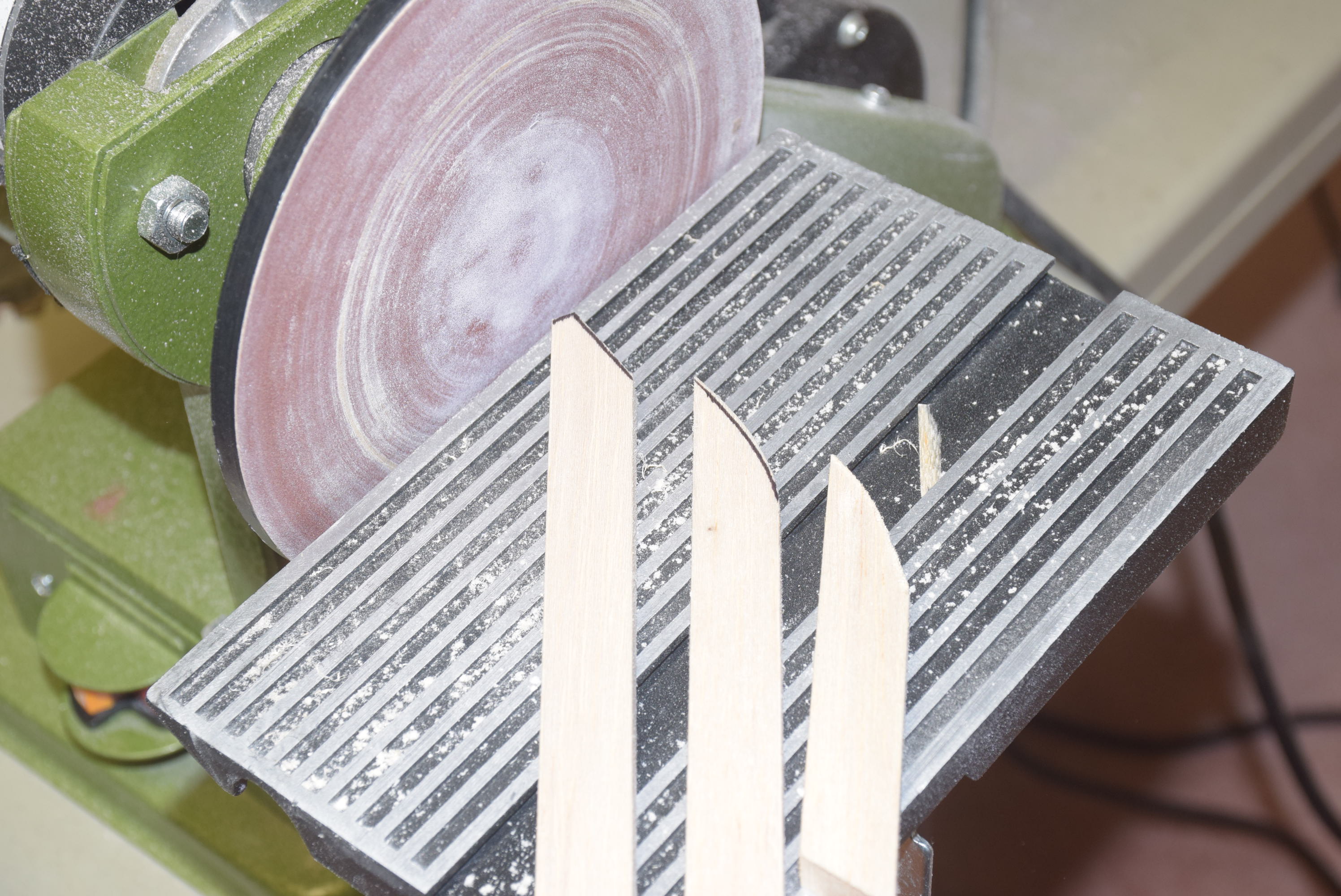
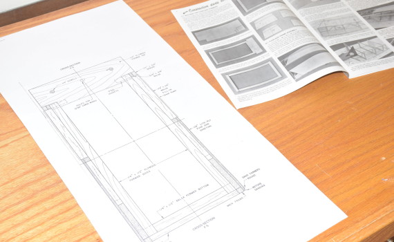
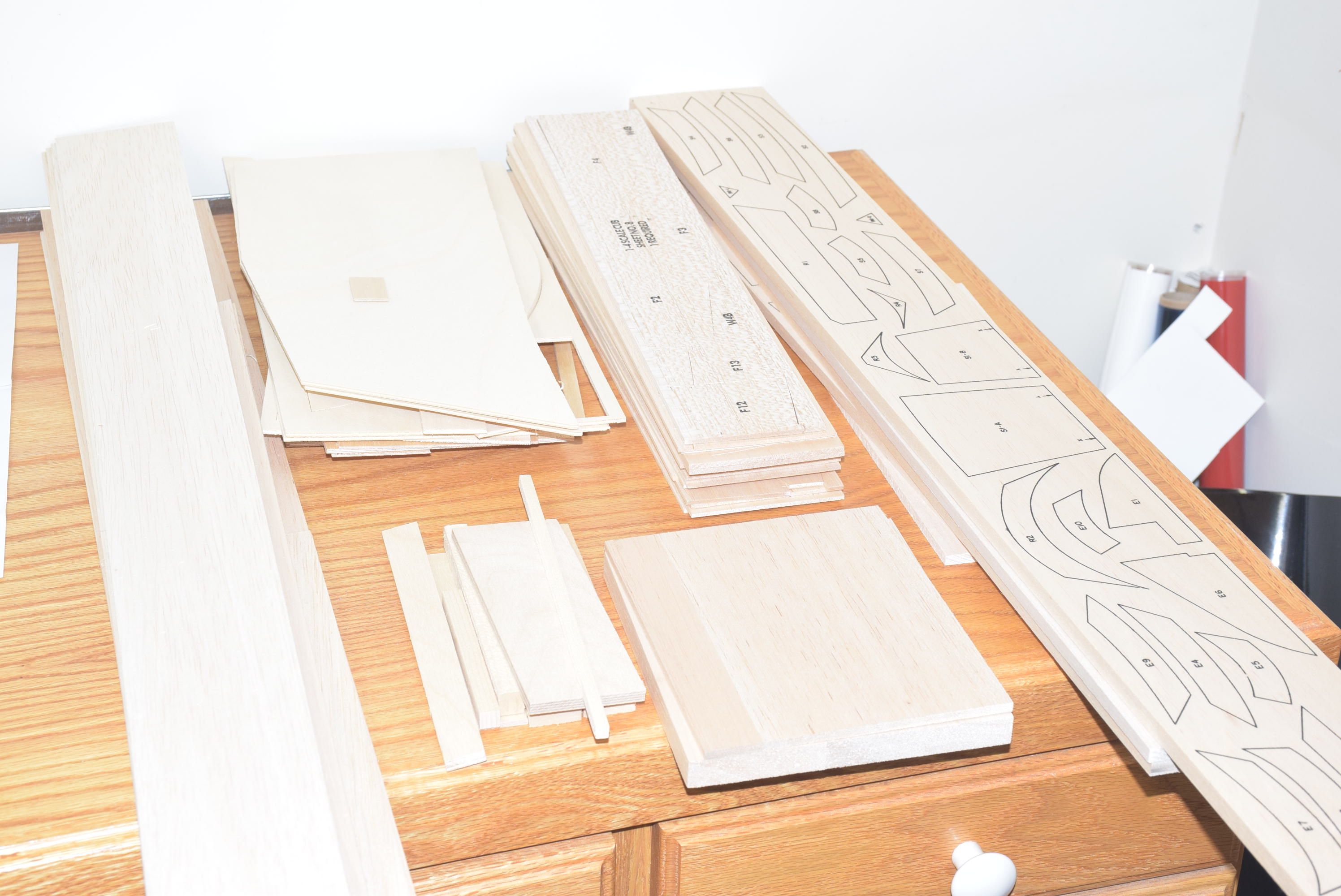
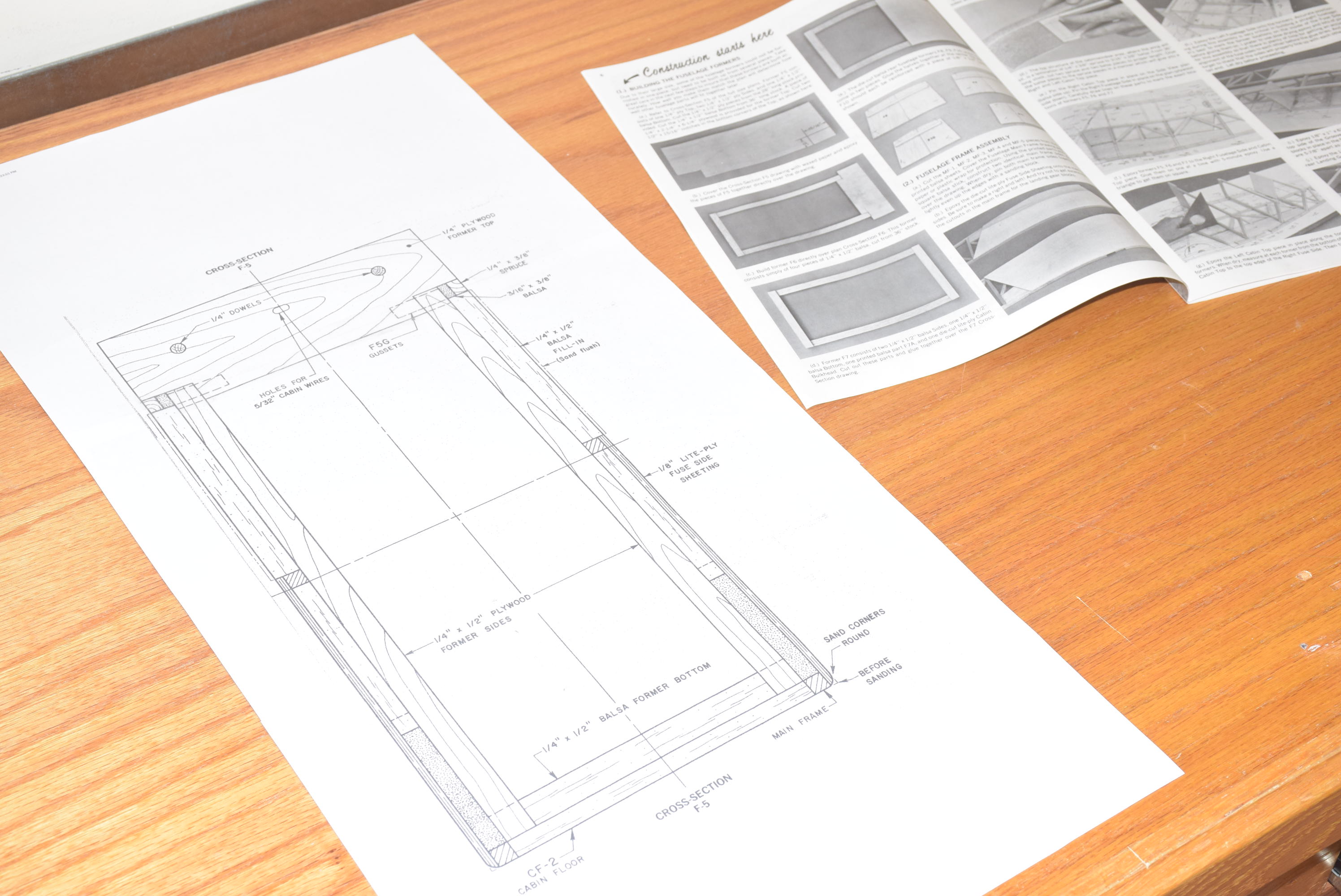
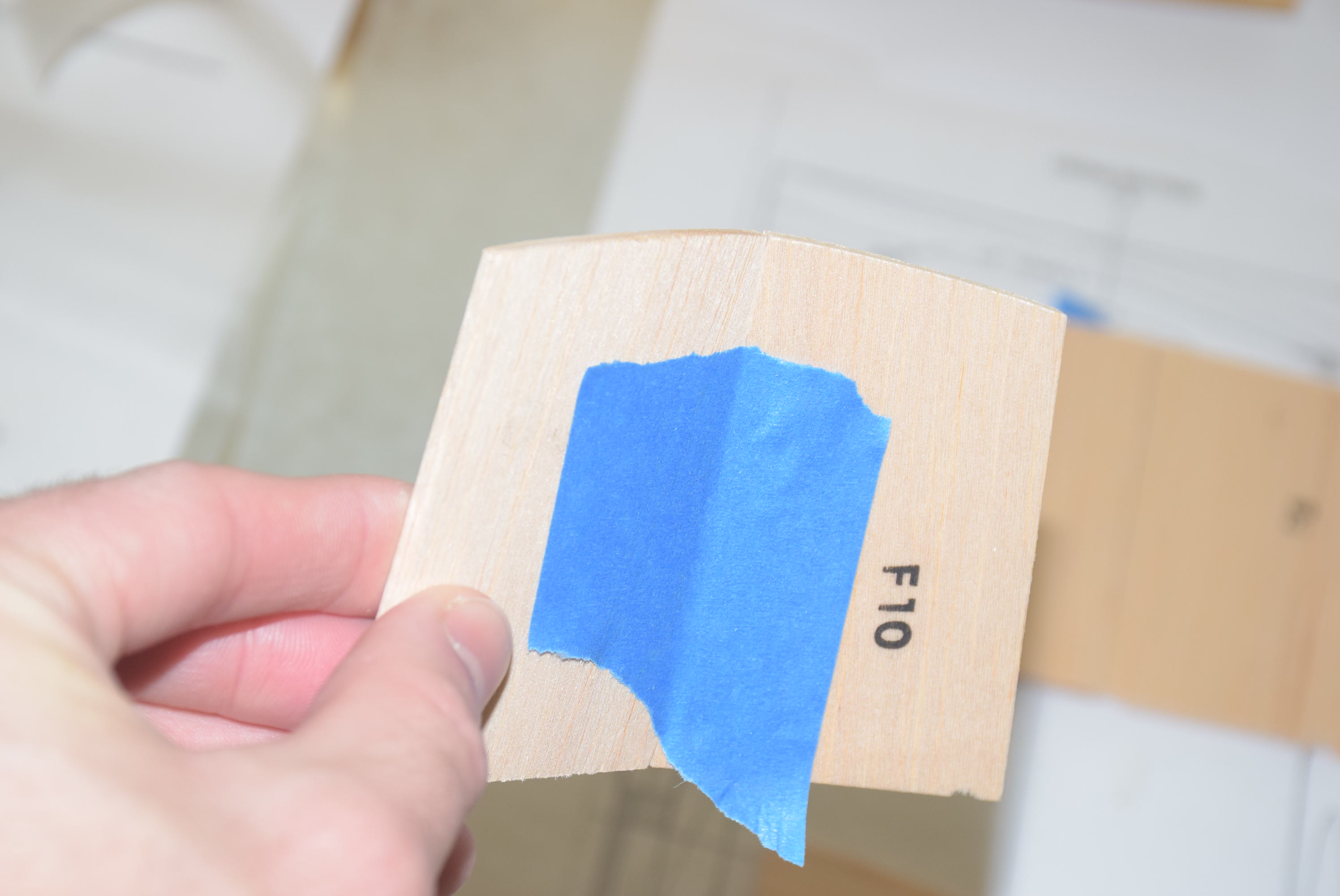
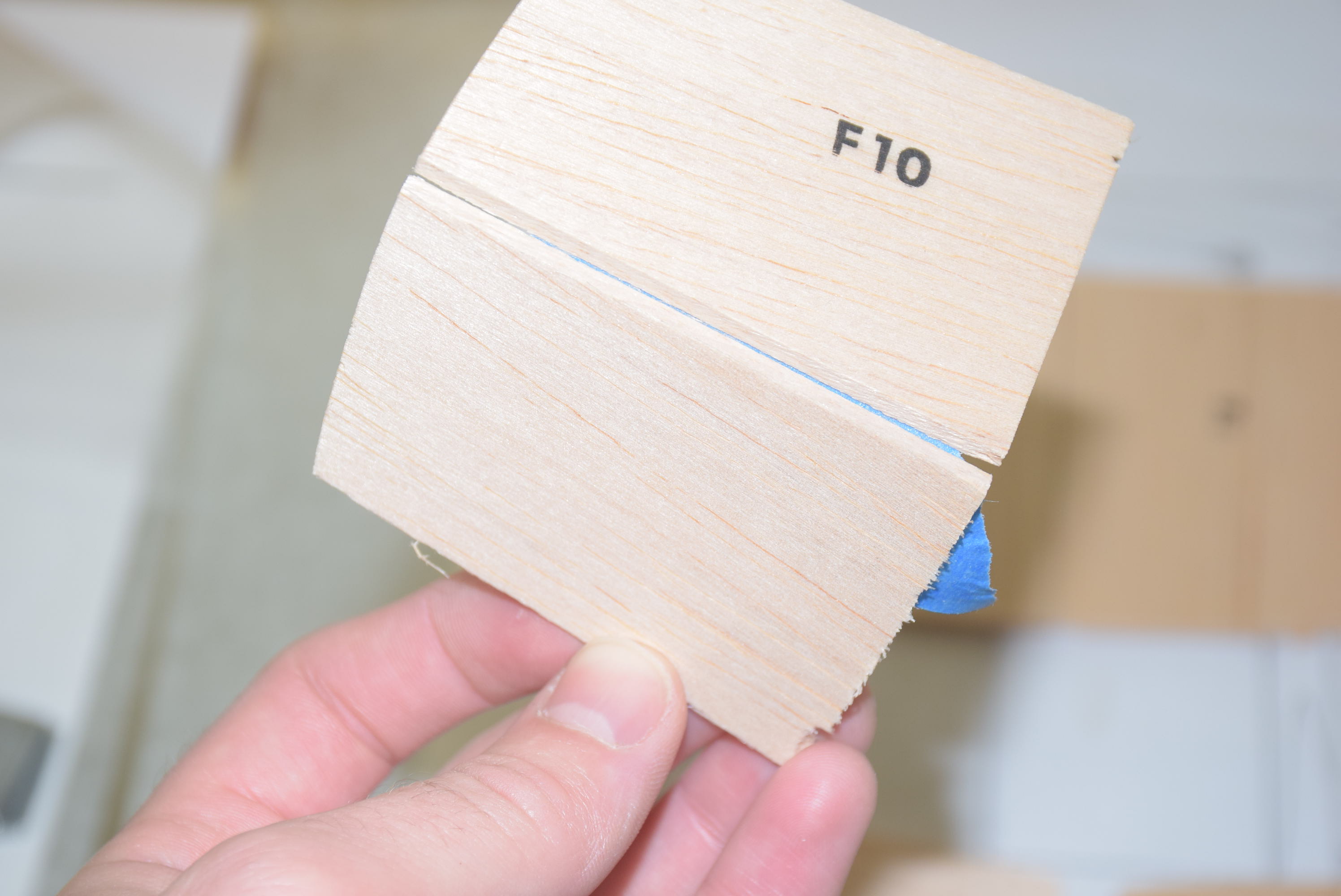
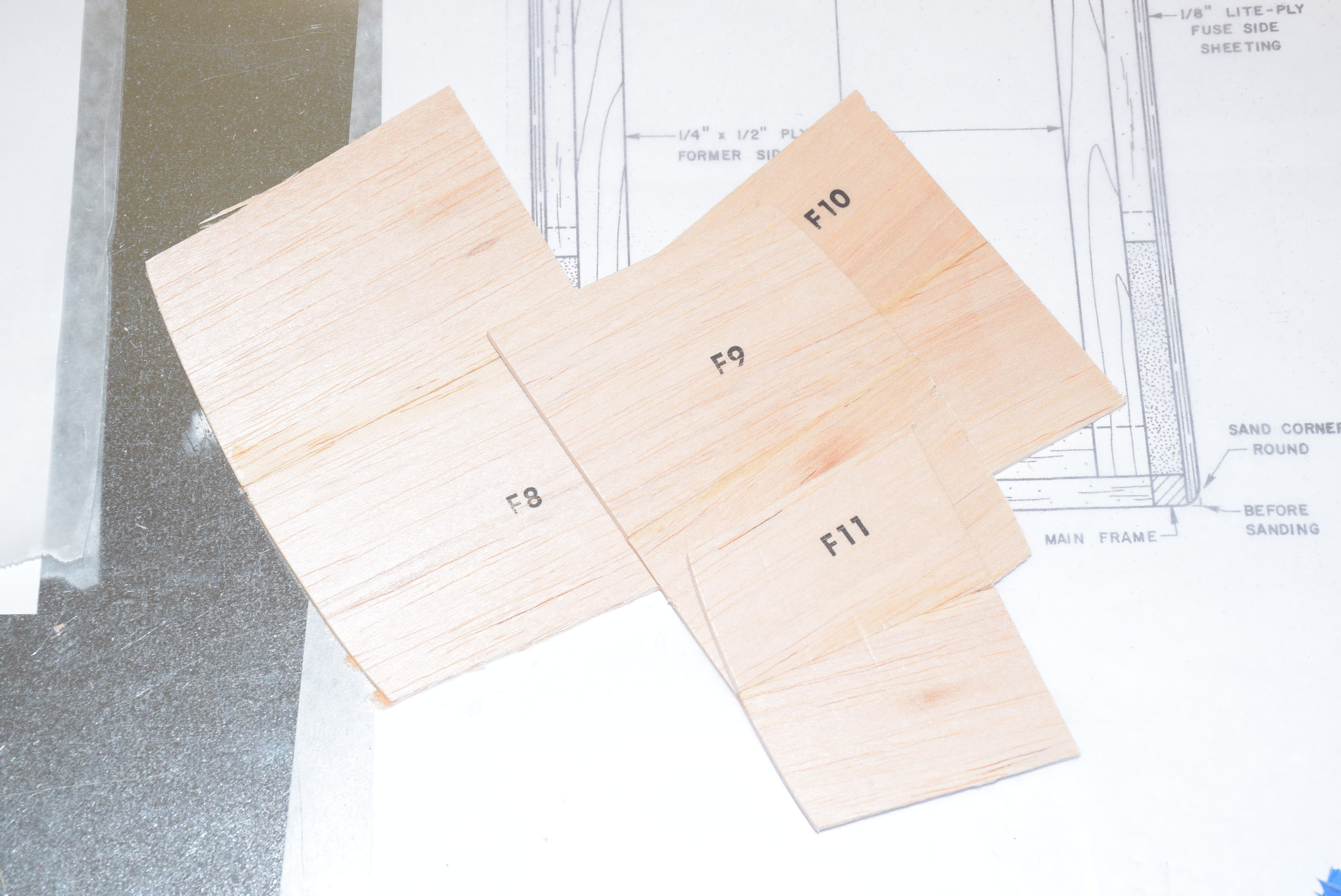
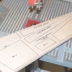
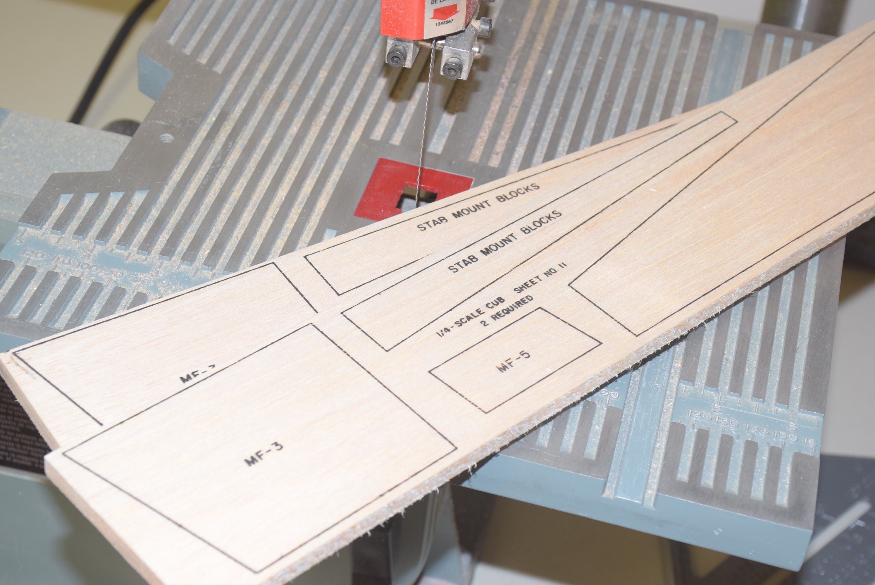
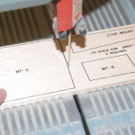
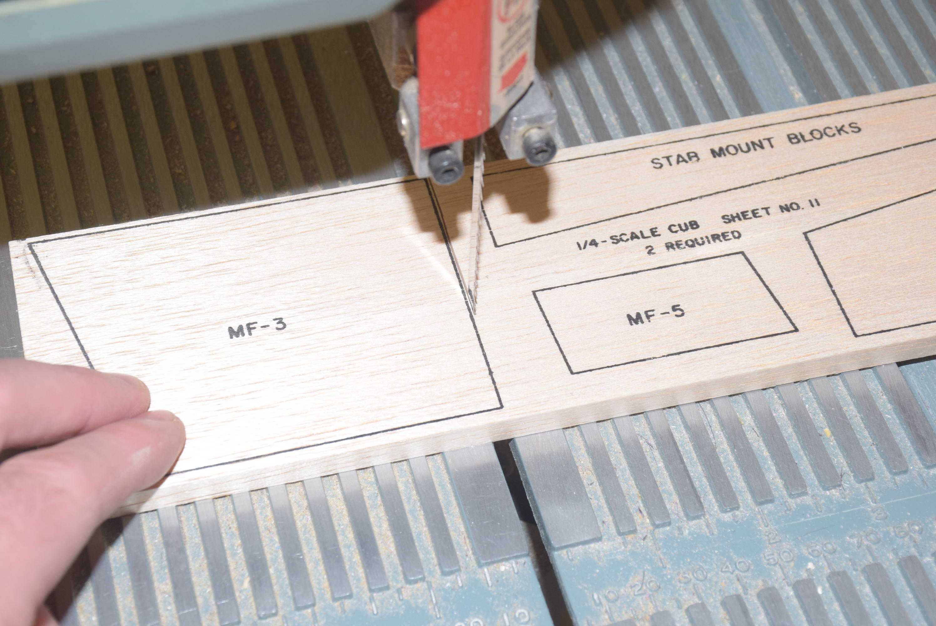
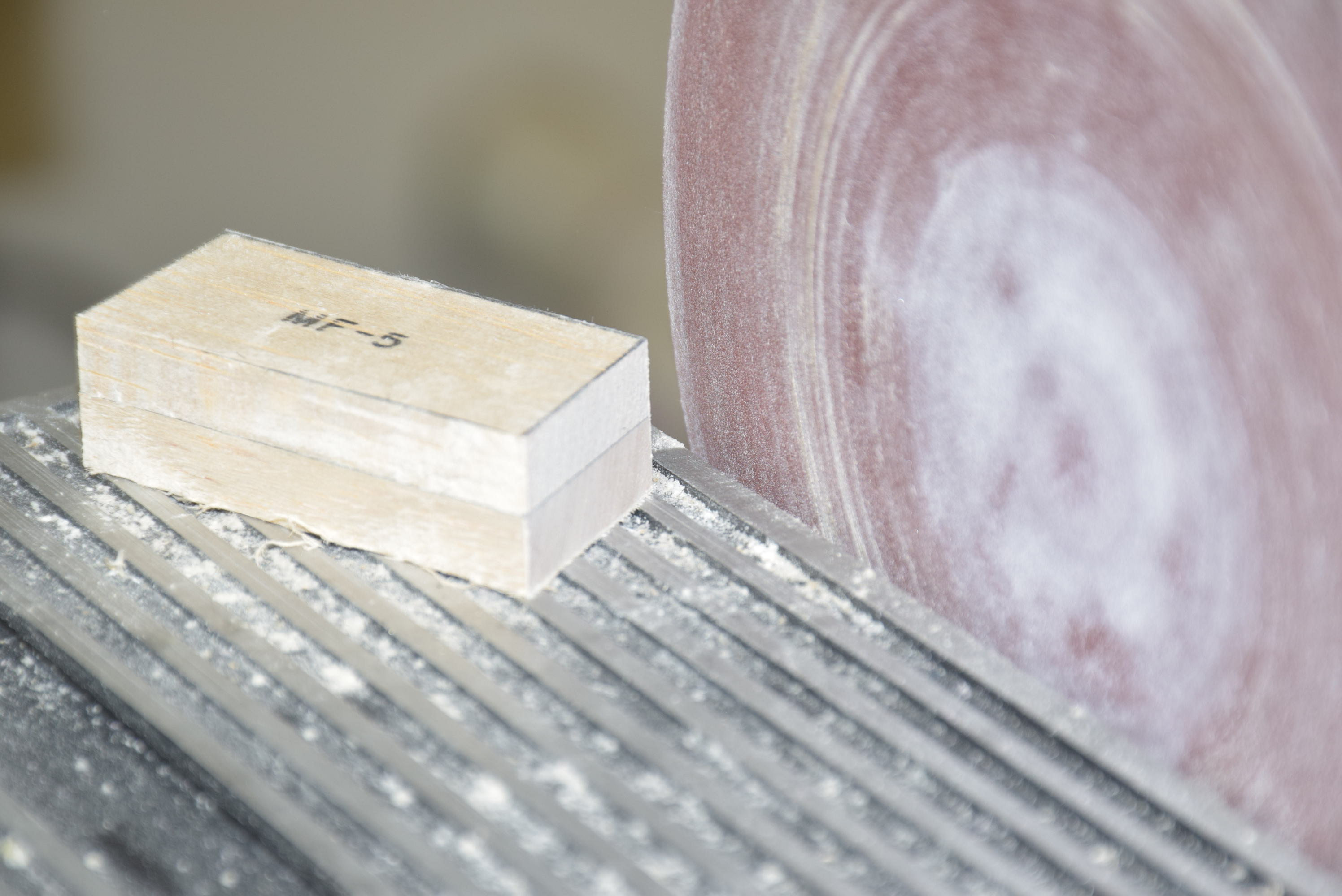
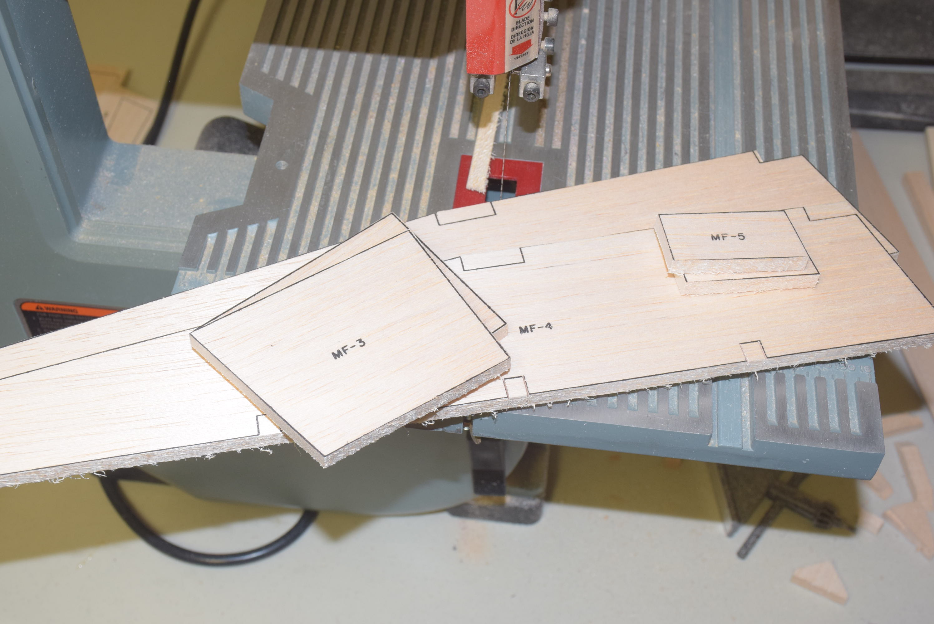
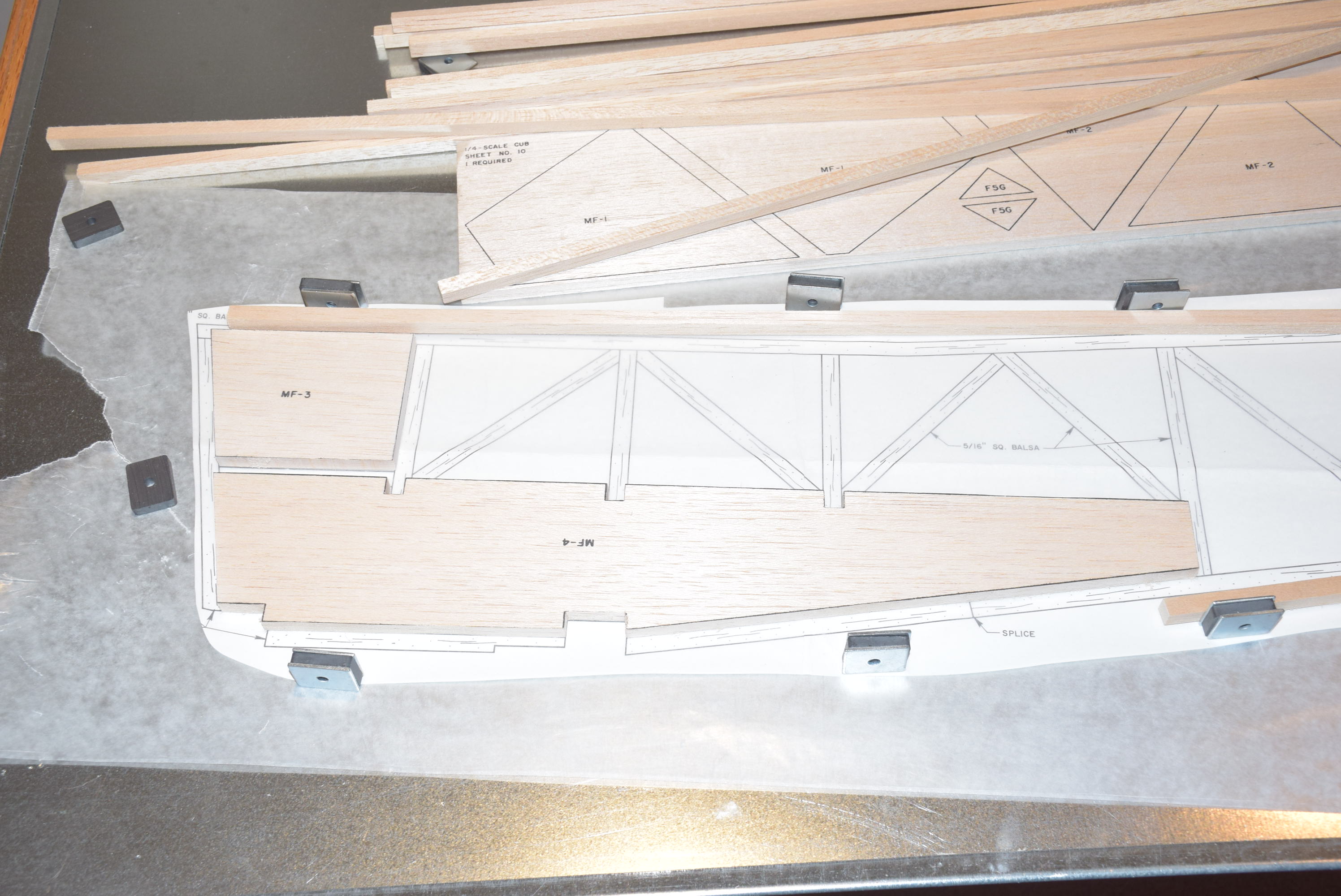
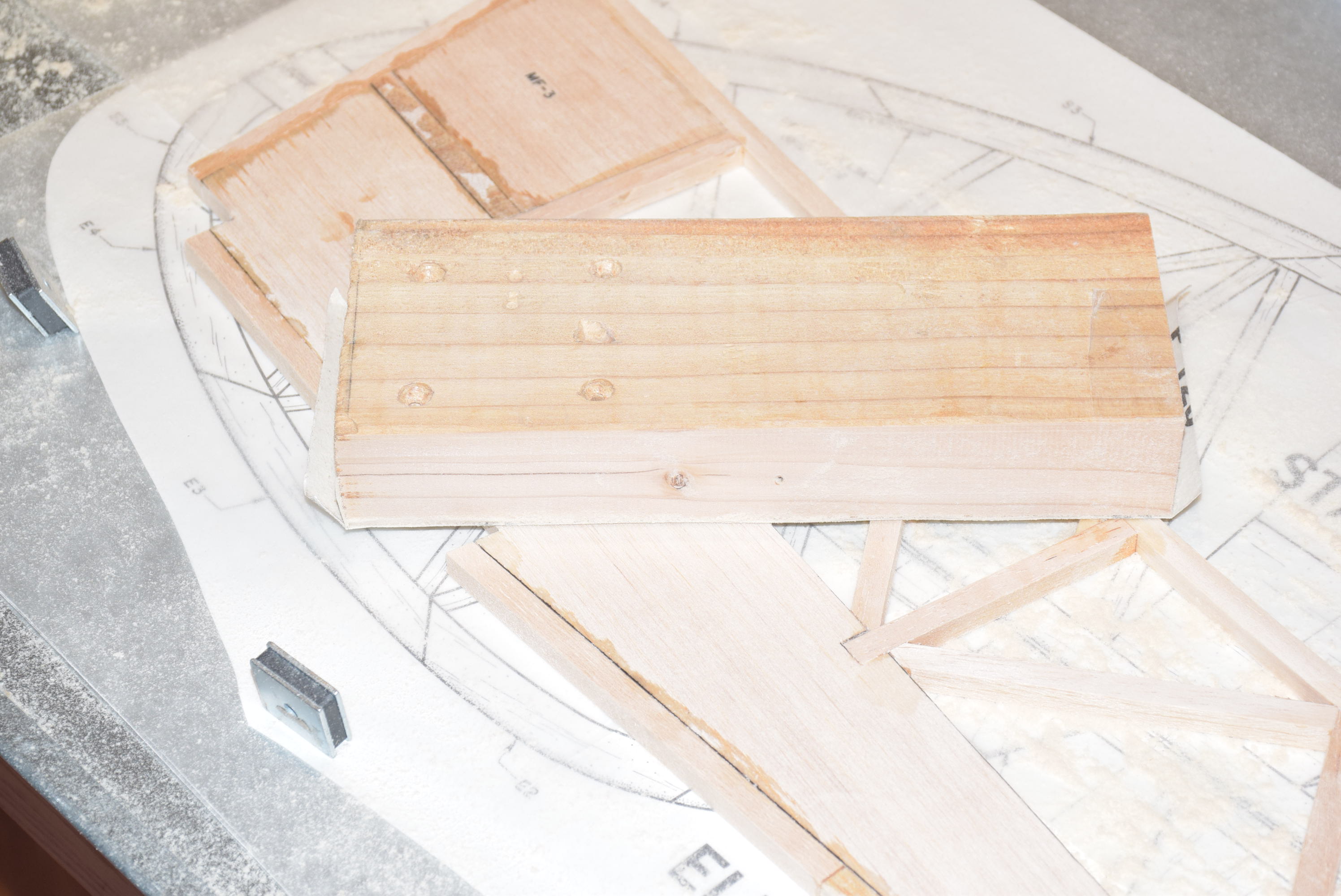
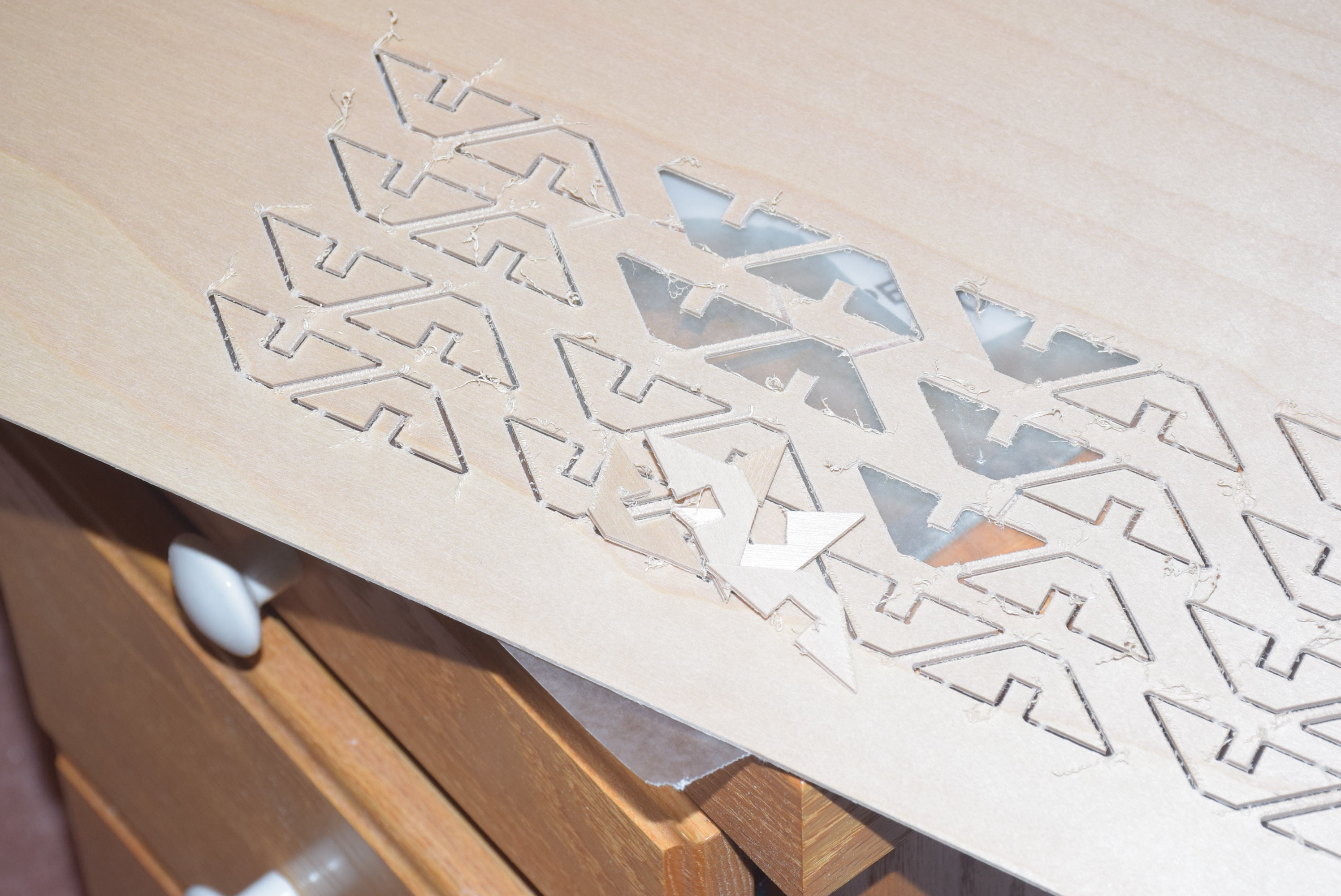
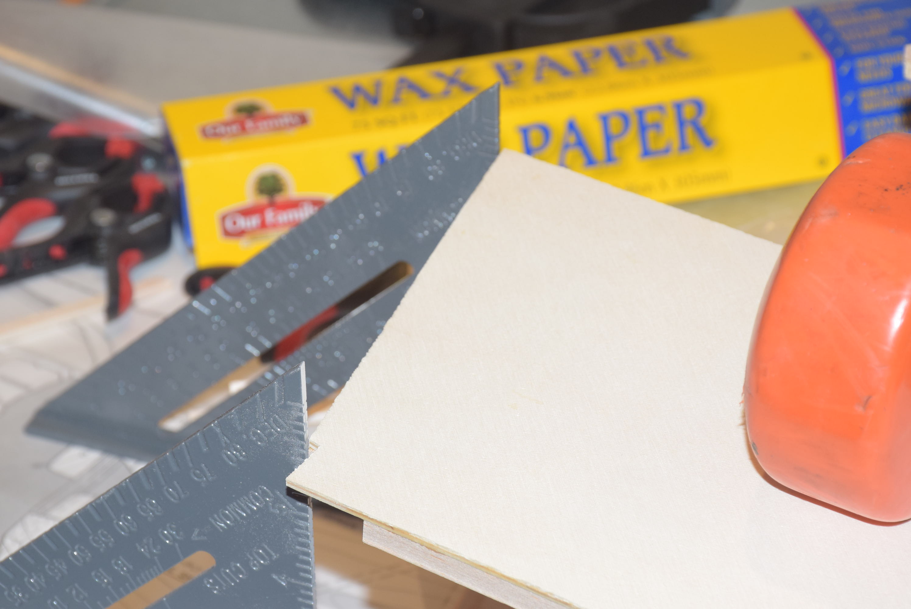
Begin with cutting out the appropriate sections of the plans and taping them together using the guides indicated on the plan. Cover the plans with wax paper and secure in place as flat as possible over your building board with magnets. There are two printed balsa parts that will need to be cut out using a band saw or scroll saw. Cut out pieces MF-3 through MF-5 from the included printed balsa sheet. Take time to cut these out as accurately as possible. Once the pieces are cut out make sure they are as equal to each other as possible – I like to stack them on top of one another and sand the larger piece until they are exactly the same. Accuracy here will aid in the building process when it comes time to glue in the formers.
-
- Cutting out printed peices
-
- Cut close to the black line
-
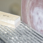
- Square up with a disc sander
-
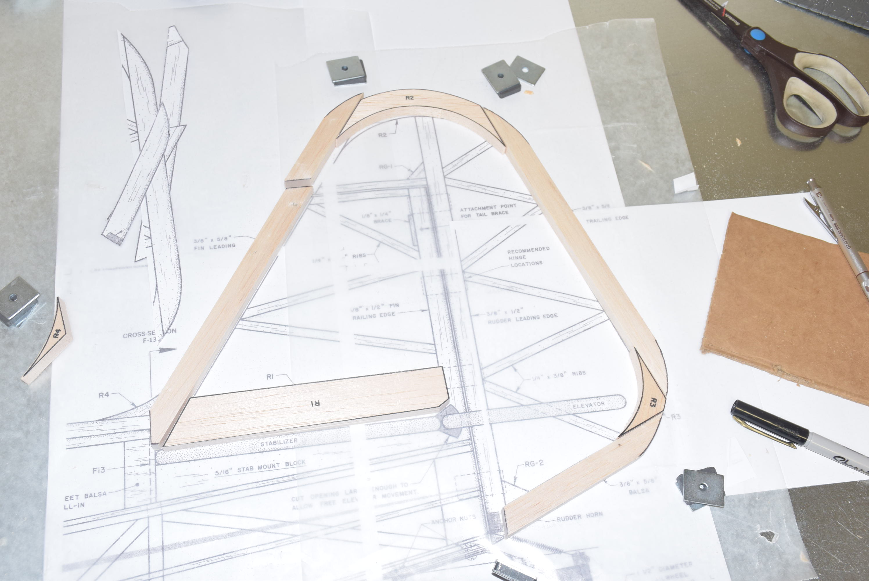
- MF-3 through MF-5
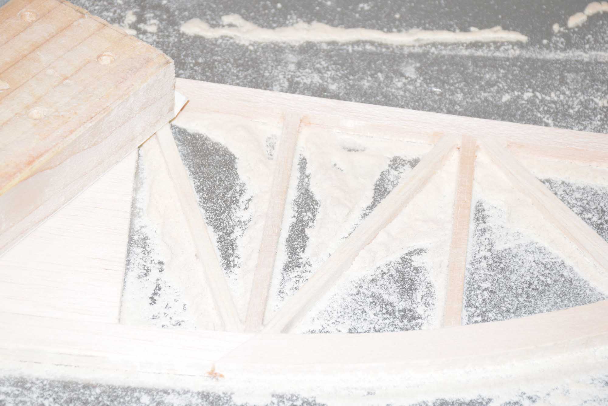
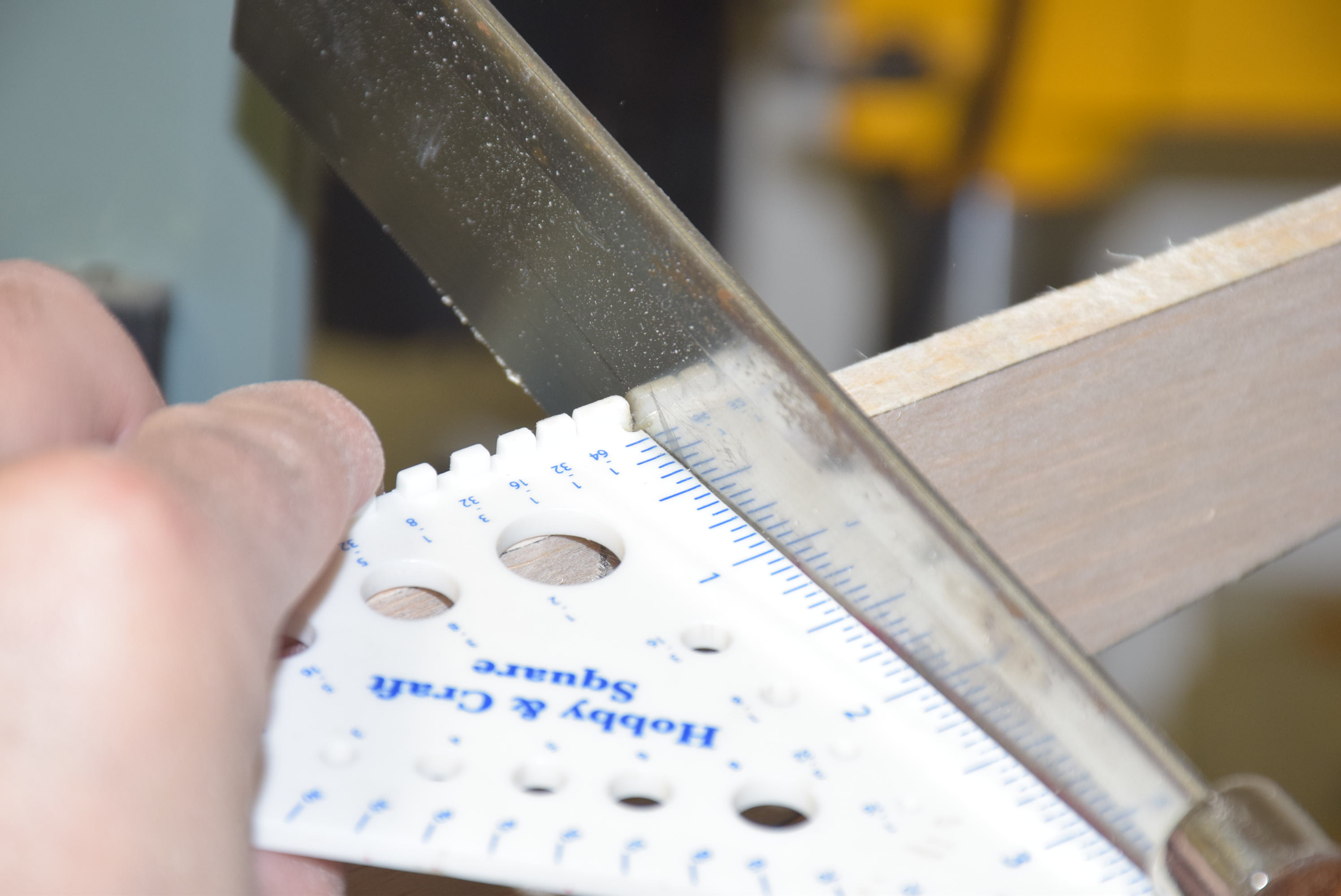
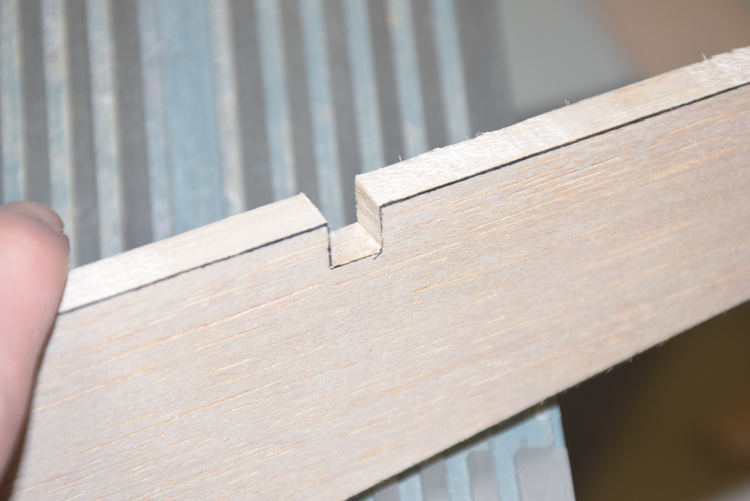
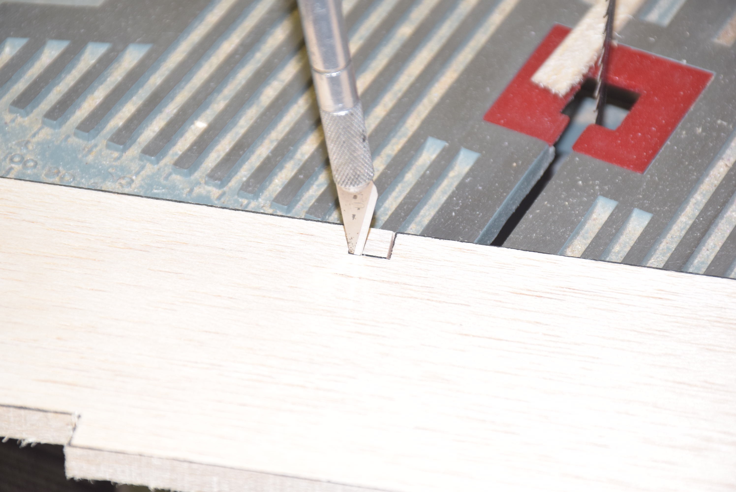
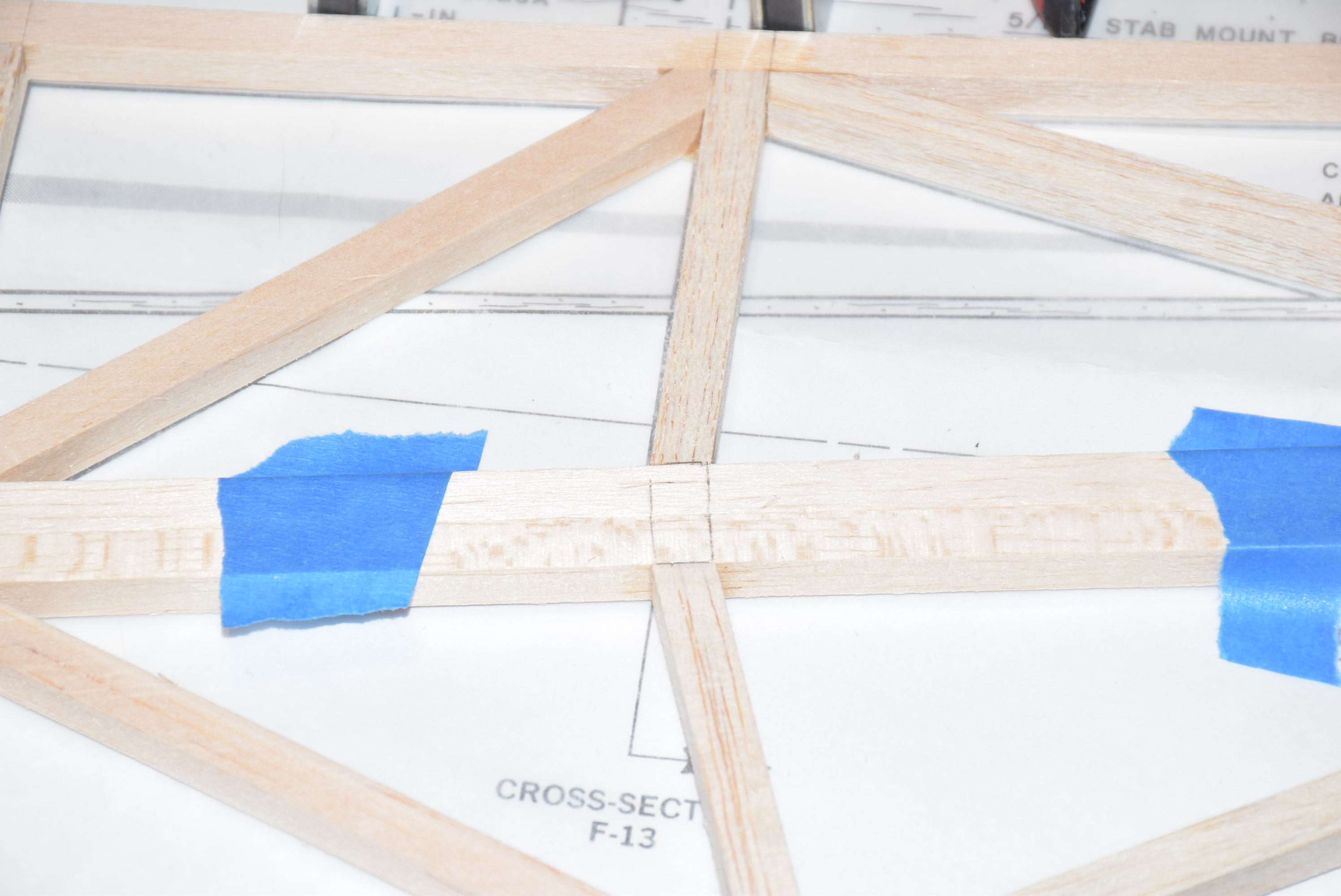
Before starting assembly of the fuselage, sort through the 5/16 square balsa sticks included with the kit and set aside the several pieces you will need to build the truss work frame. Try to sort the balsa according to grain structure and hardness. There a few cutouts that need to be made on MF-4, use a razor saw and a square to make sure you cuts are straight and accurate for the cross grain cuts. Next, just use a sharp no. 11 blade to easily cut along the grain to finish the cutout.
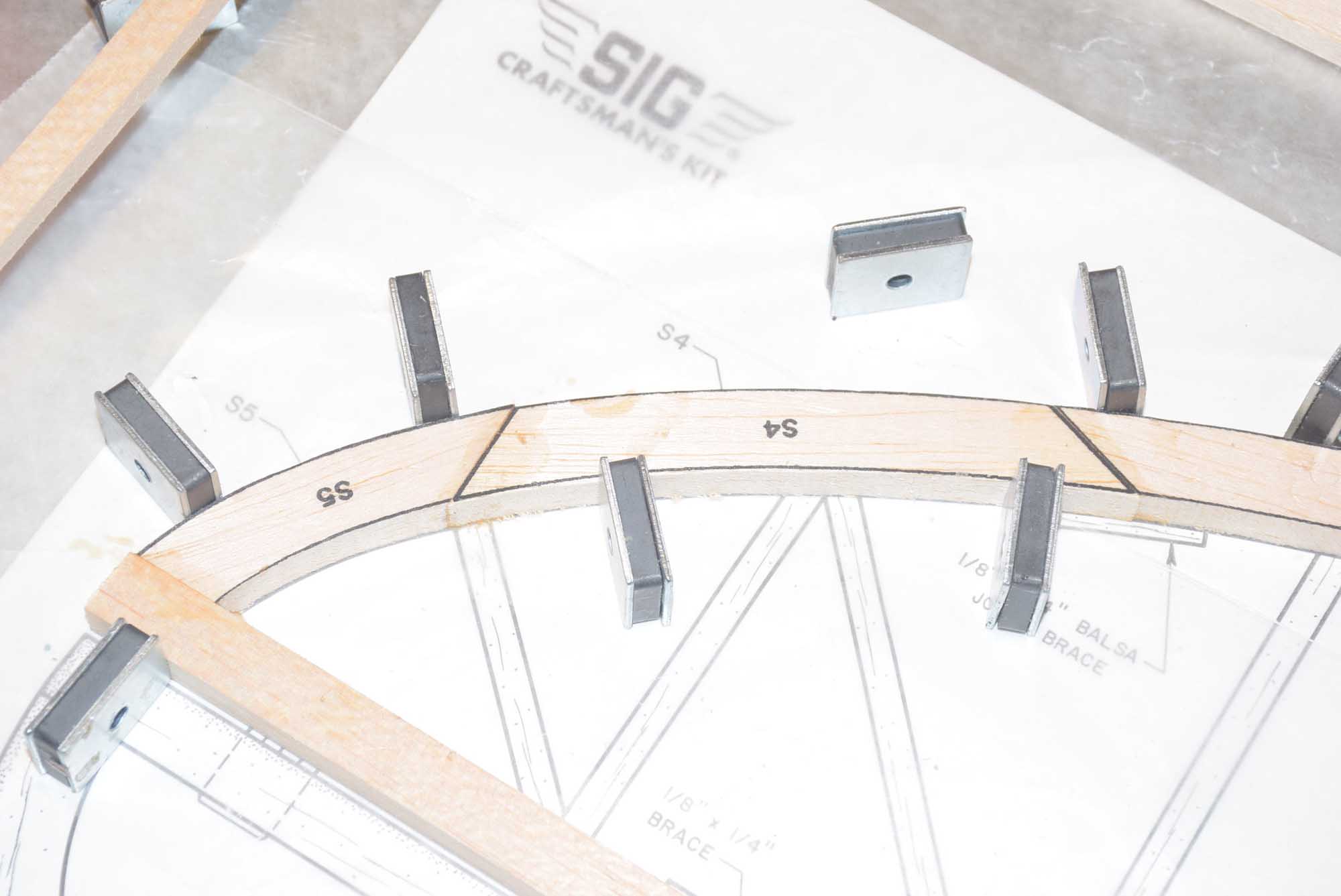
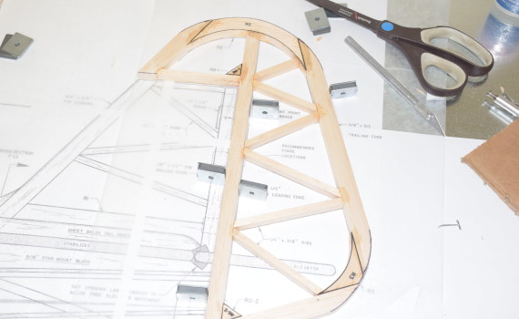
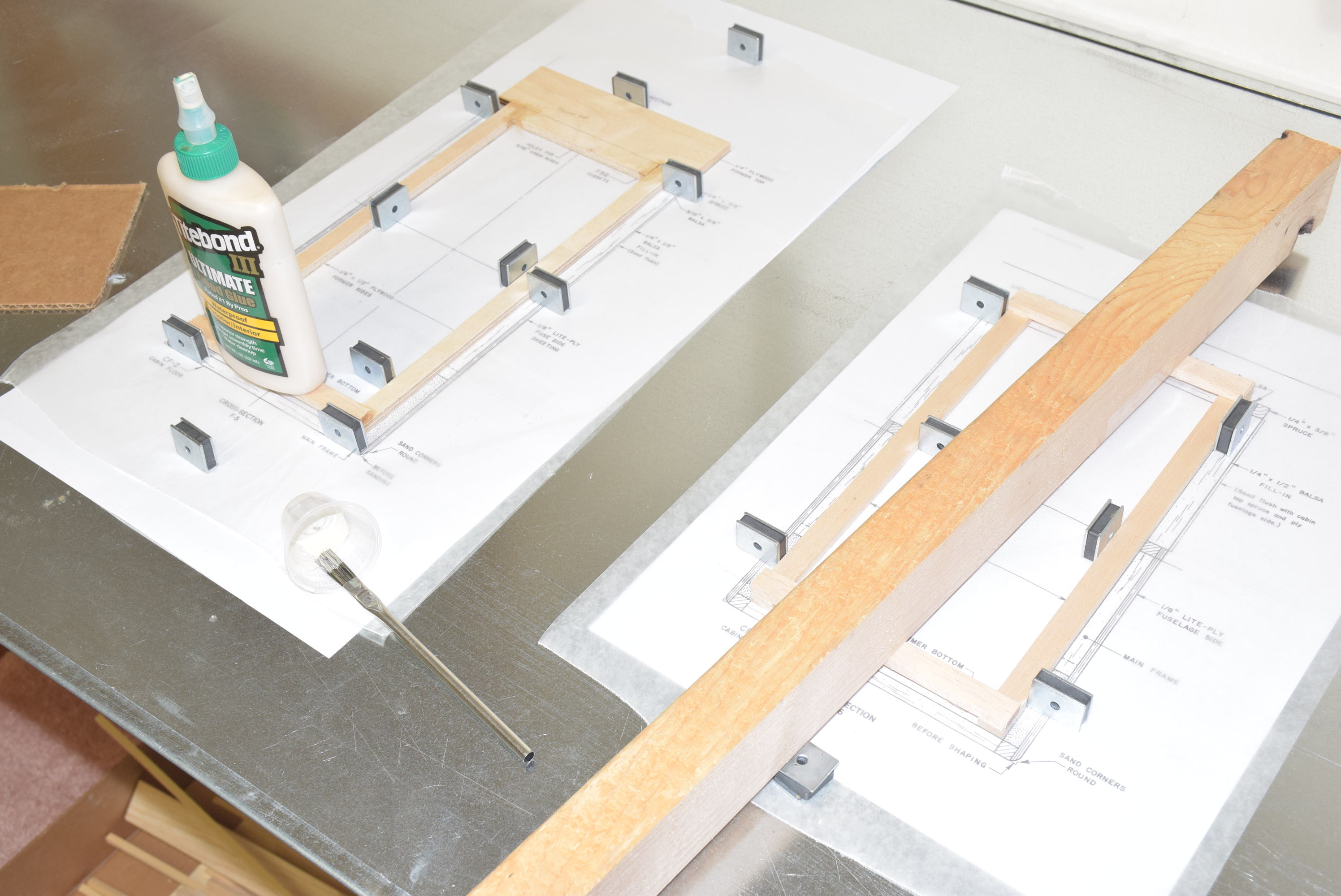
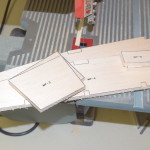
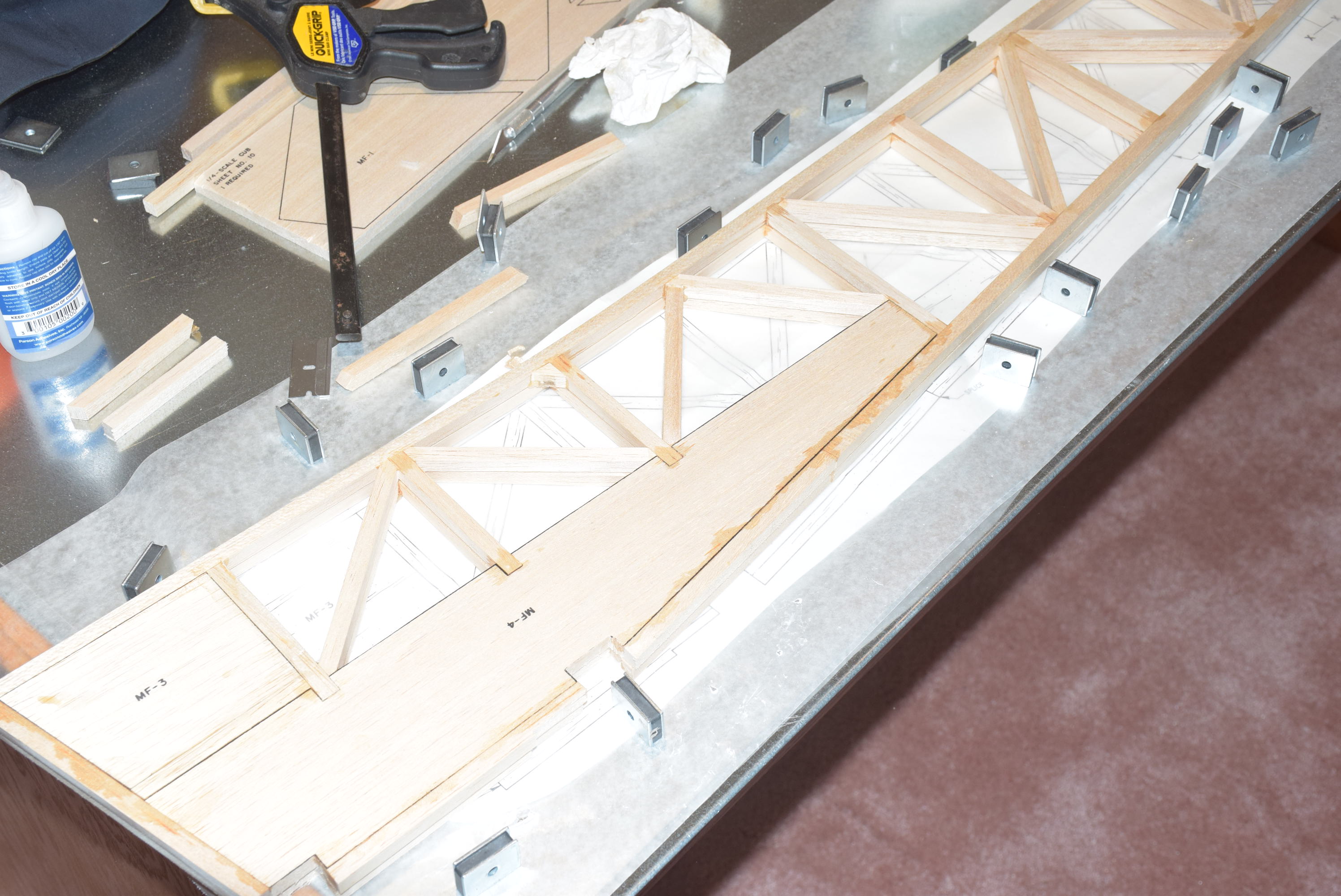
Begin with placing pieces MF-3, MF-4, and MF-5 over the plans. Secure in place with magnets or pins. Also begin laying in the 5/16 square balsa sticks along the plans to see how everything lines up. One thing to note, when building the truss work sides start with the longest pieces and work to the shorter ones. This will be the most efficient way to utilize the balsa included with the kit.
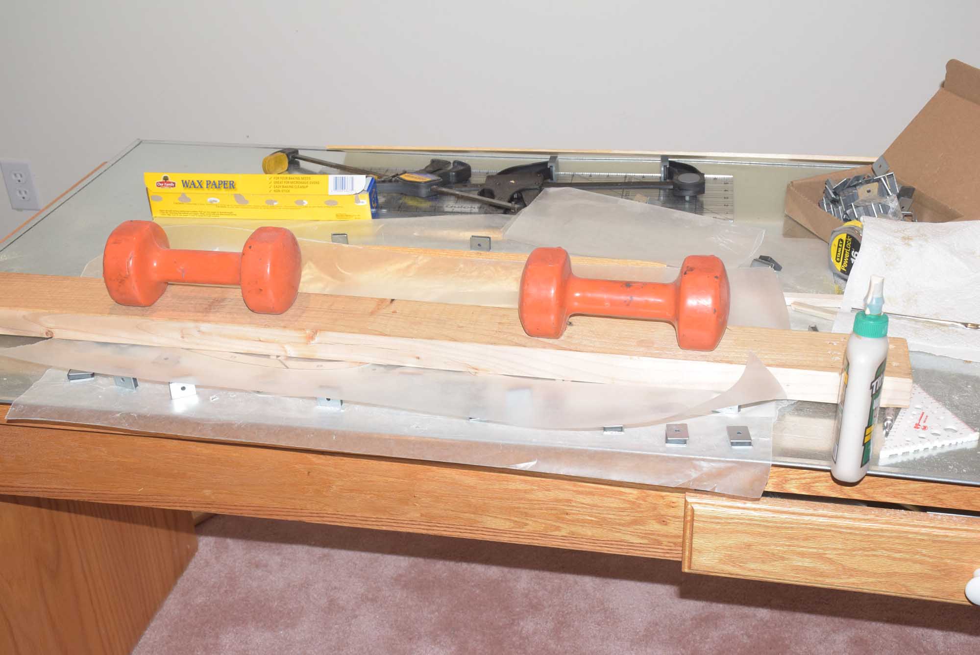
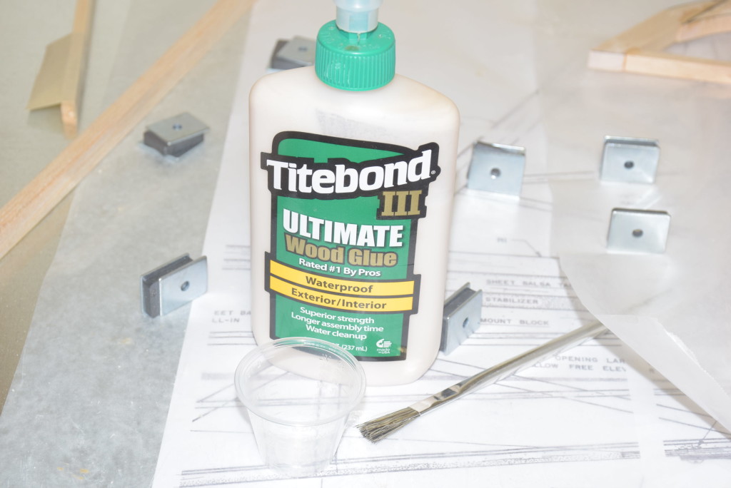
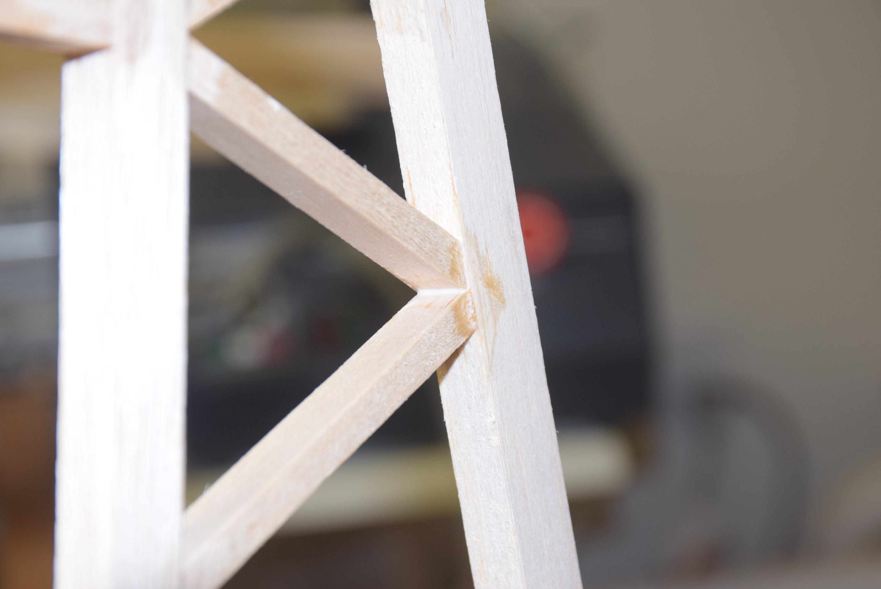
Begin by gluing in the straight pieces of the truss work sides moving from the front of the fuselage toward the back. Tack them in place with CA glue for now. During the rest of the framing use a high quality wood glue. Wood glue will take a little longer to dry but the joint will be very strong yet allow a little flex in the joint where needed. Use clamps on the 5/16 square stock where it has to make a shallow curve according to the plans. I used wood glue here and allowed it to dry over night.
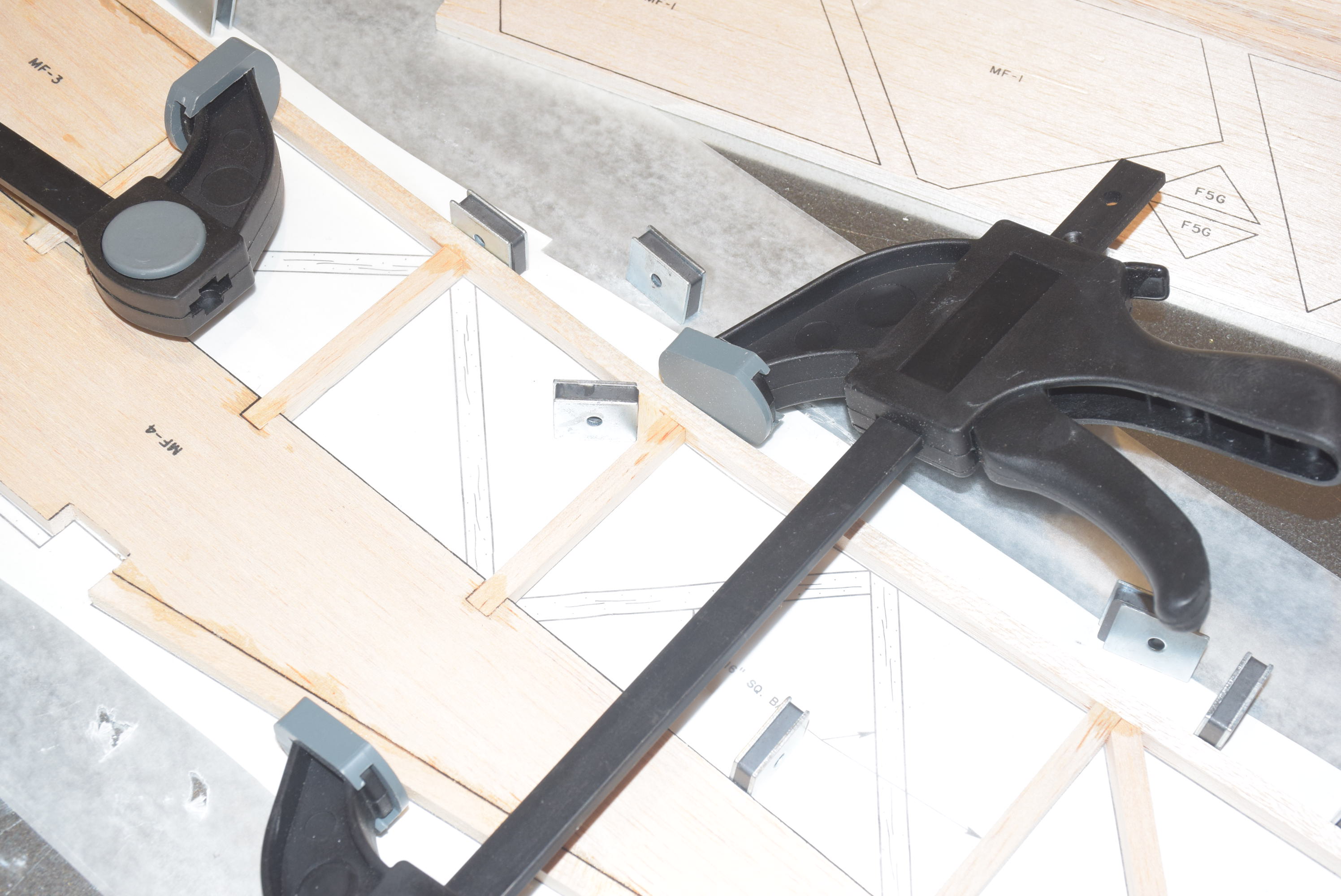
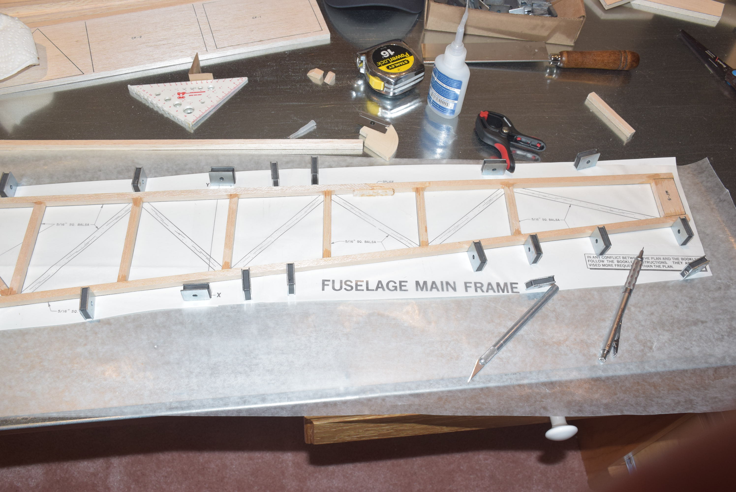
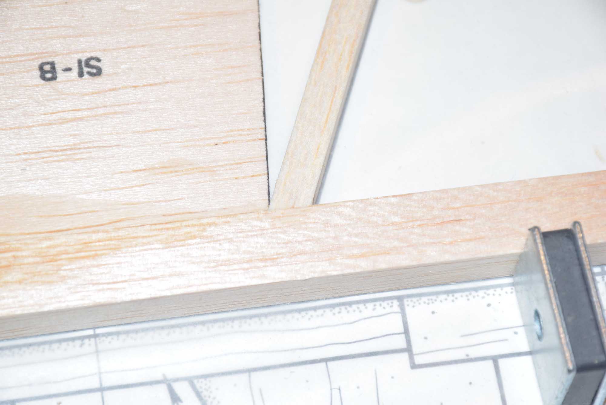
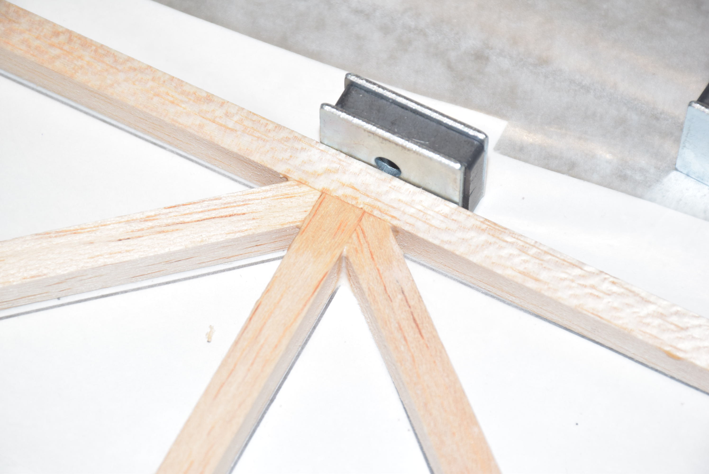
Once the main pieces are dry you can begin working on the diagonal frame work to construct the rest of the truss style fuselage. Again we will use a tip from Airfield Models to cut very accurate angles on the balsa sticks.
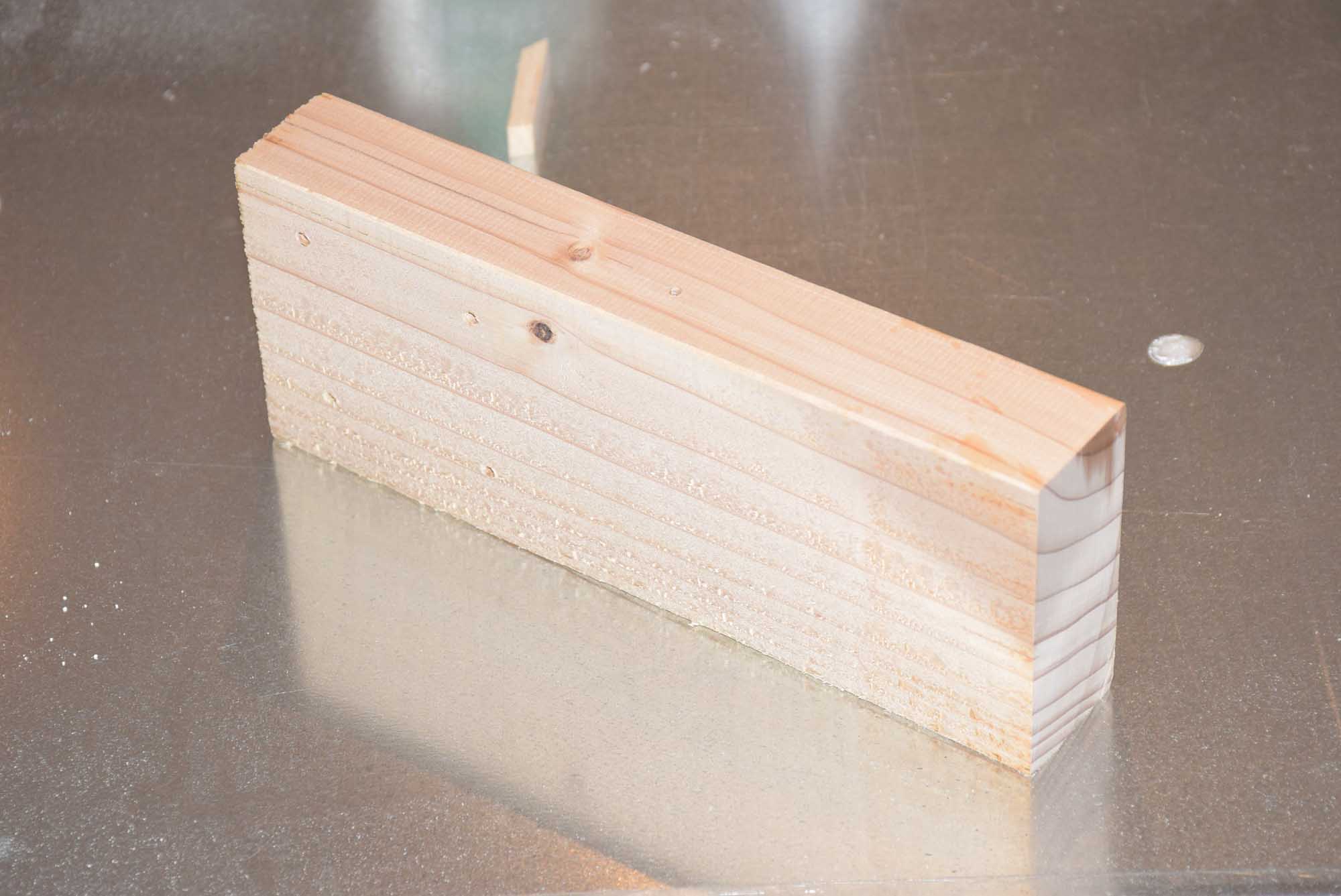
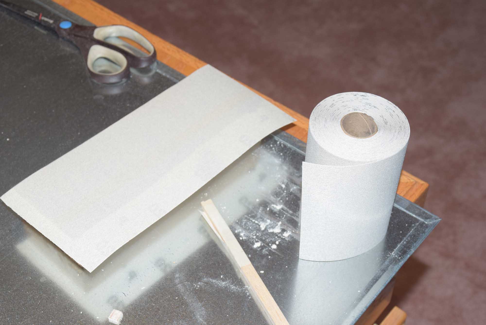
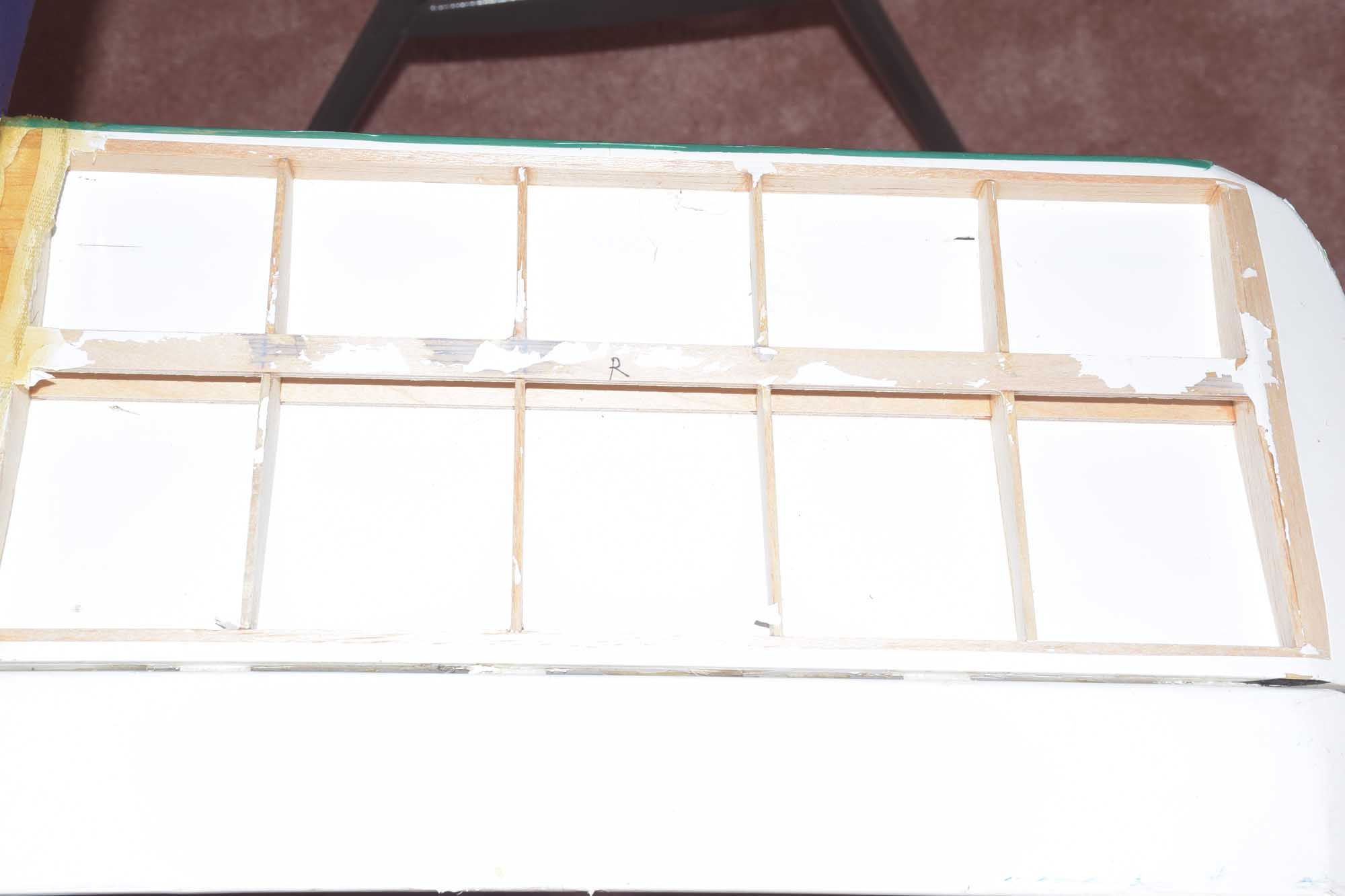
Once the fuselage truss work is completed for both fuselage sides (you can build both sides directly over the plans – no need to worry about a “right” and “left” at this point), lightly sand them to a nice smooth finish with a sanding block. I made a sanding block from a piece of 2×4 that was run through an edge jointer on all four sides. We want it to be very flat and each face square to each other. I used 120 grit for the initial sanding over all the joints. No need to press hard, just let the weight of the block do the work for you. Finish with 320 or higher grit for a smooth surface.
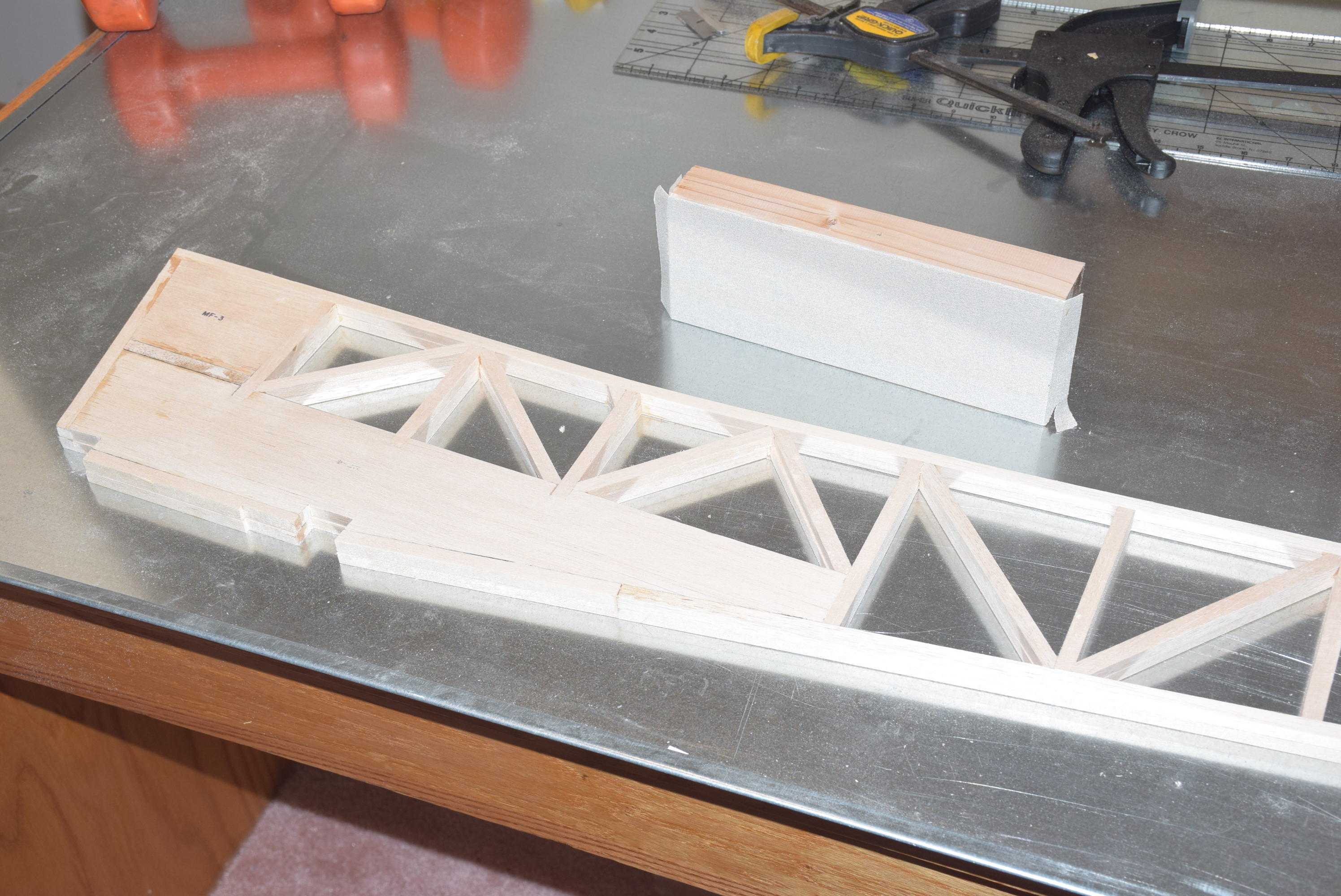
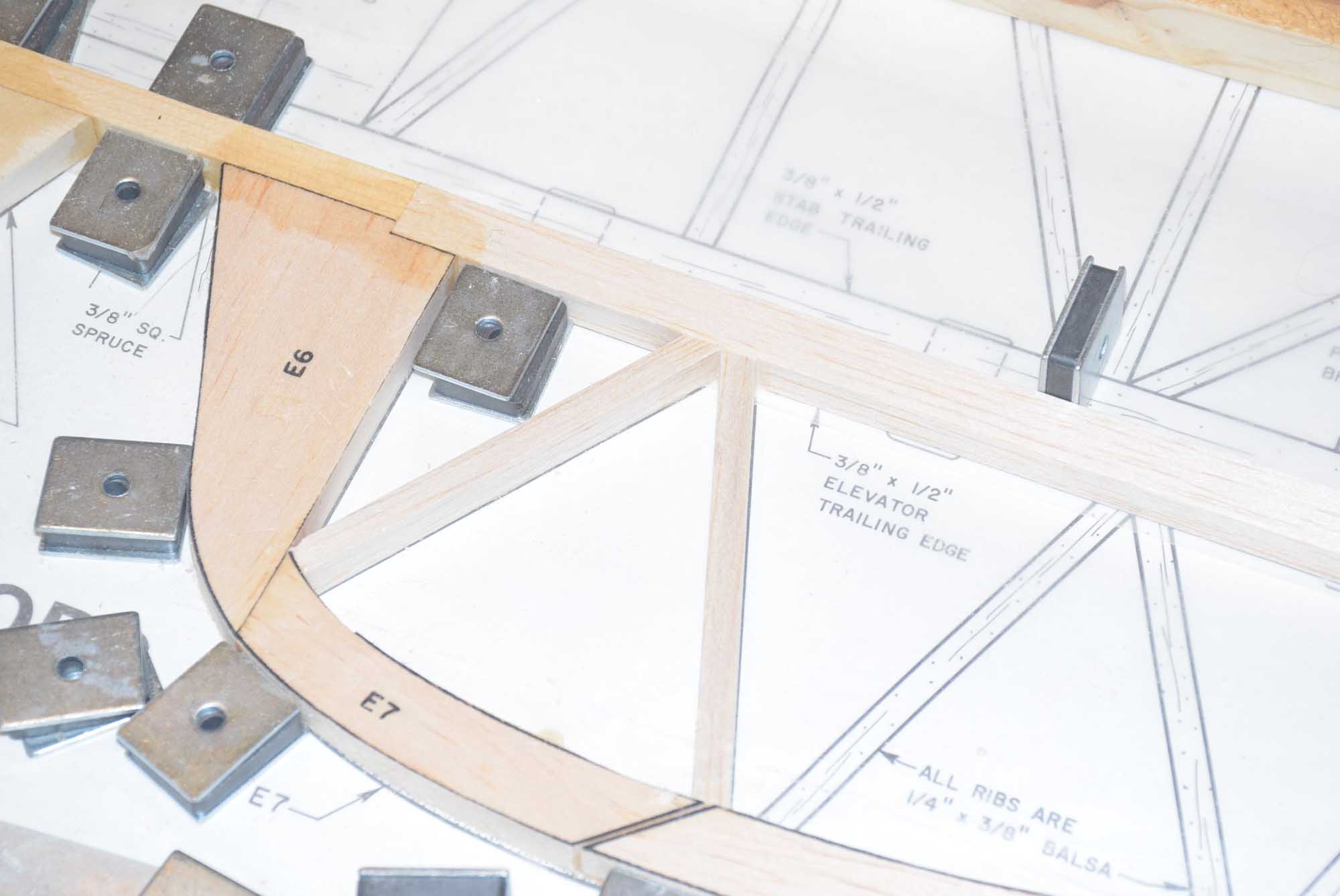
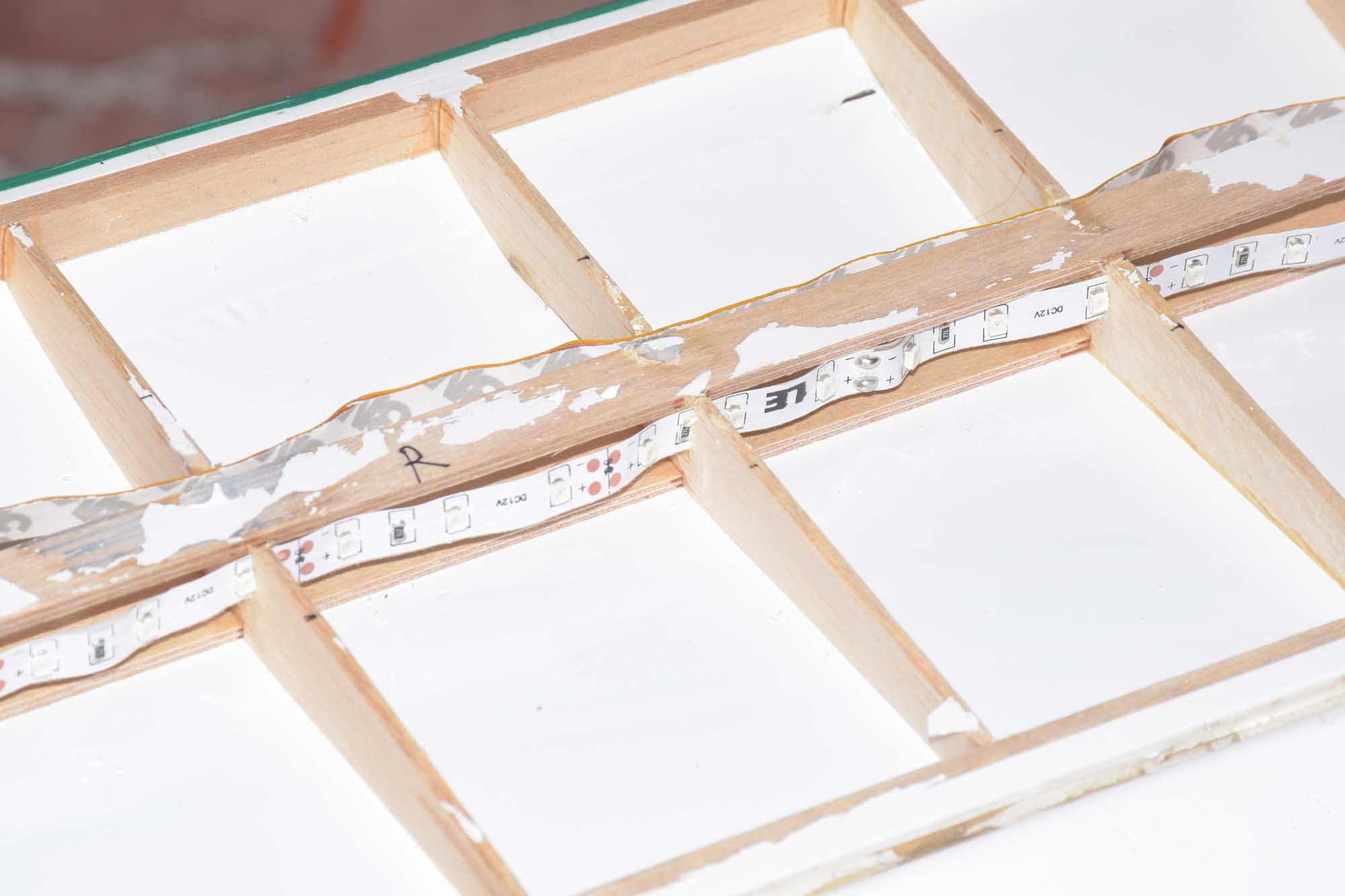
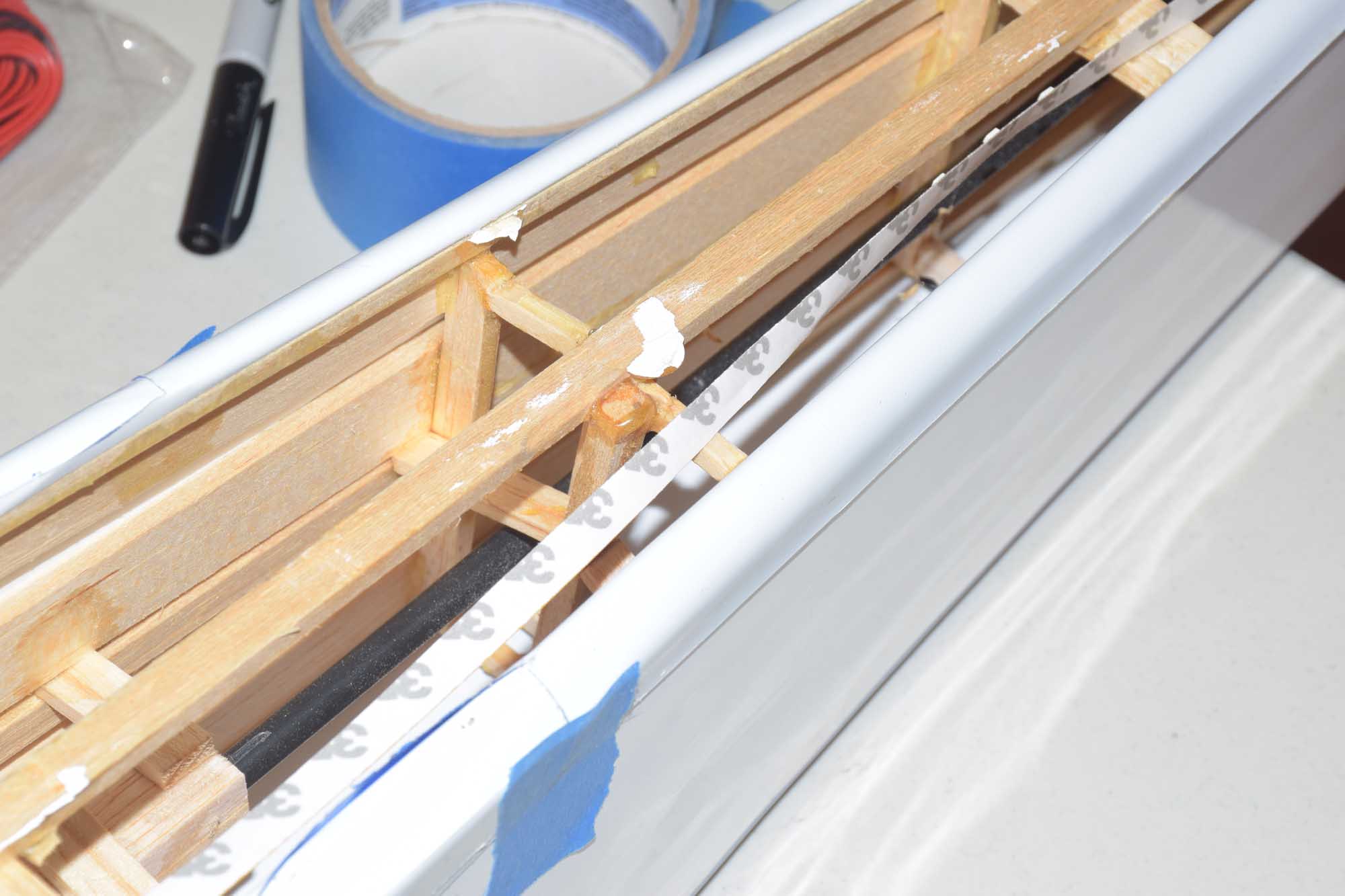
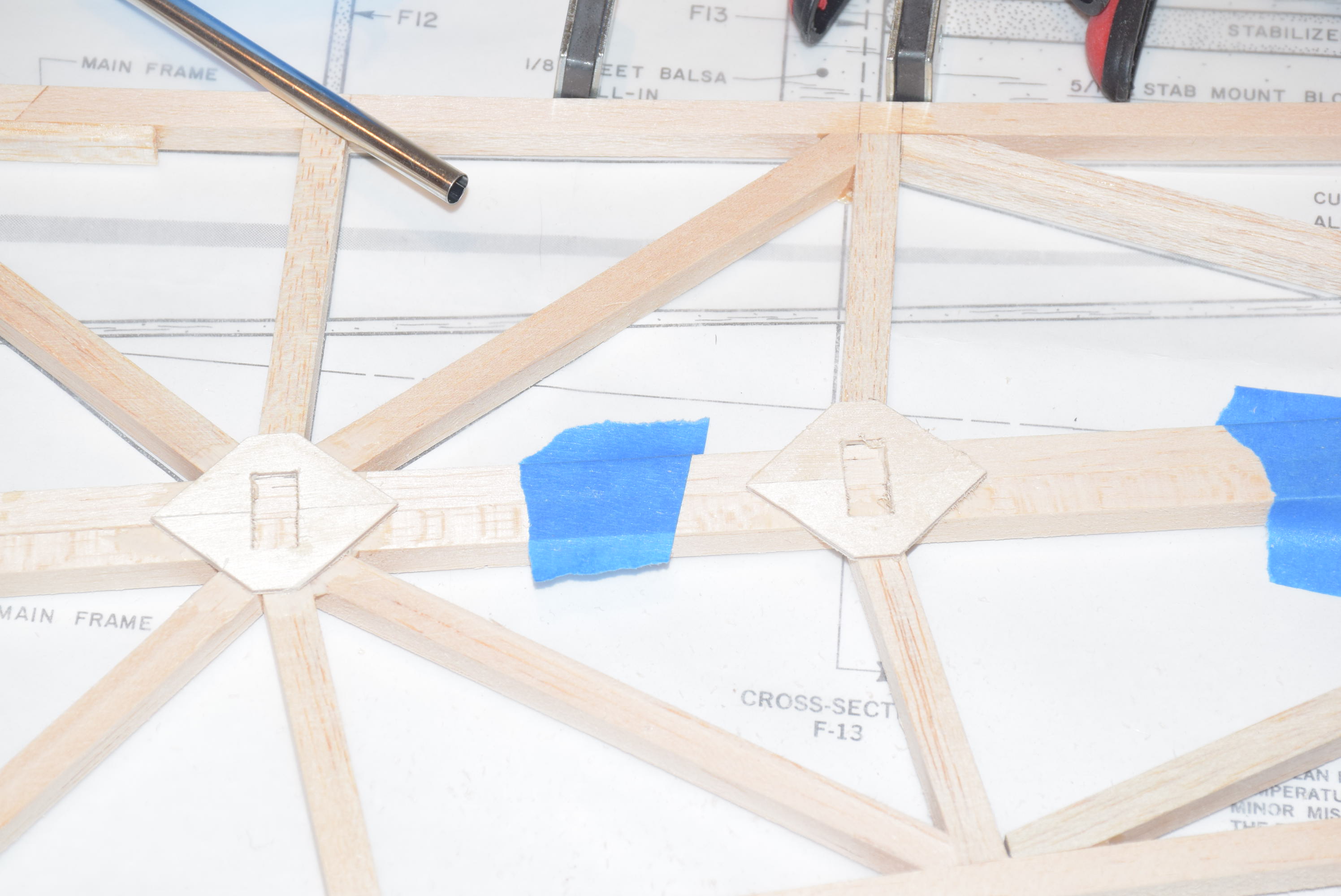
Another feature I decided to utilize was the use of gussets on the bottom of the truss fuselage sides. Adding gussets will add a tremendous amount of strength with only a very small weight penalty. Airfield Models has a template you can download for several common balsa sizes. I used the 5/16 size for the Sig J-3 1/4 Scale Cub.
I used 1/16 plywood for mine and had several cut out on a CNC machine. Glue them in place as shown in the photos below. Use of clamps while they dry will ensure they stay in position.
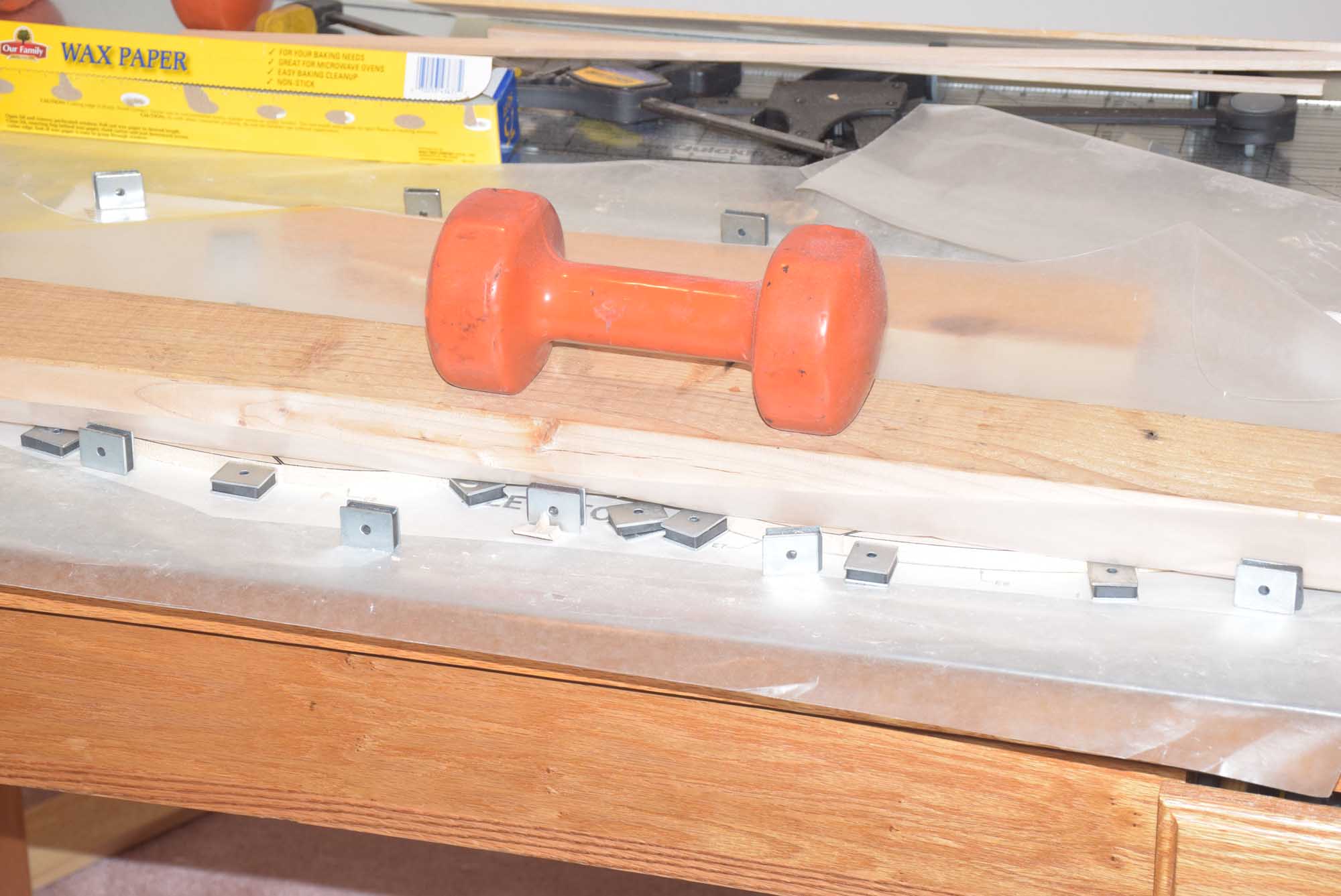
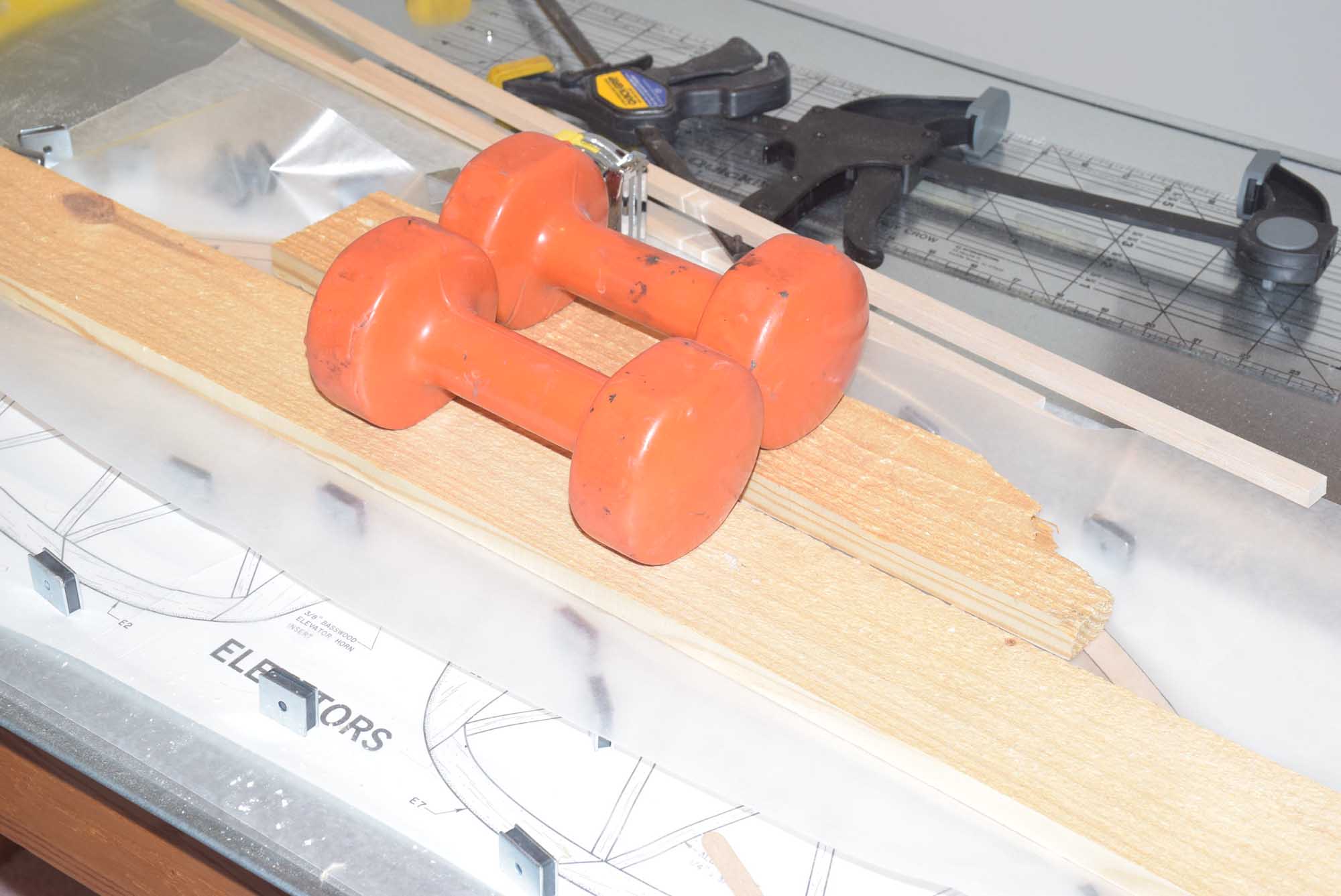
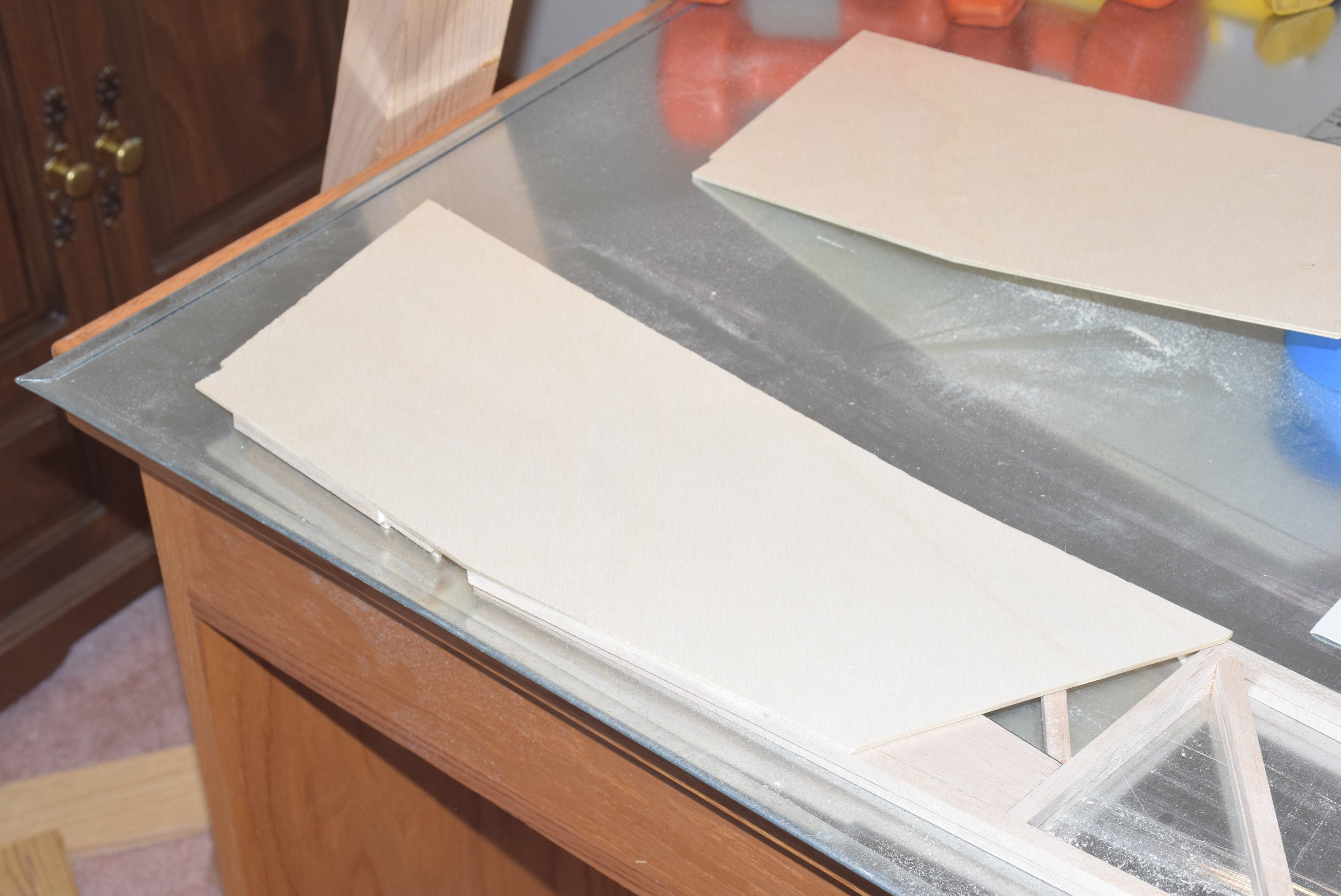
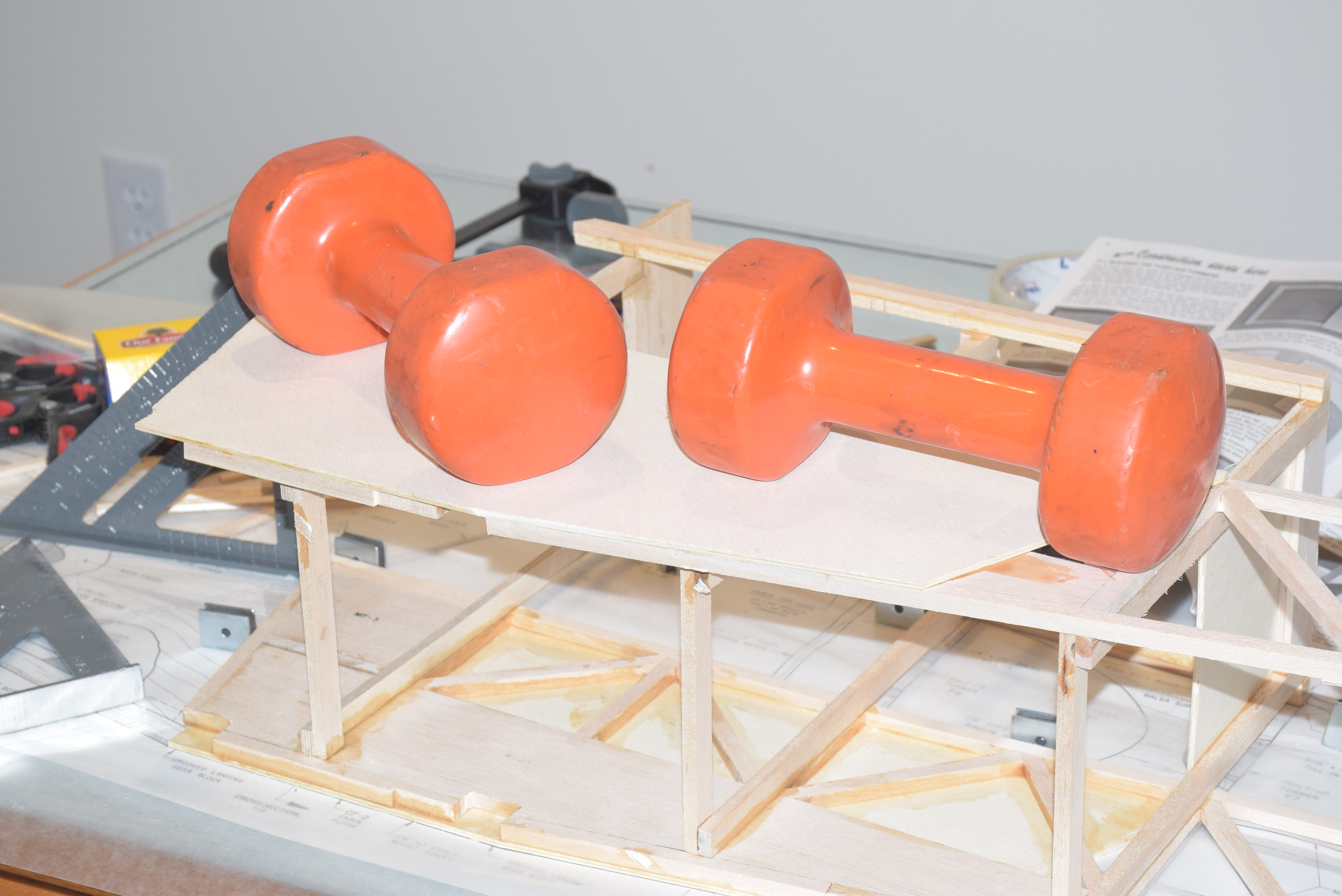
Once the truss work frames are finished and the gussets are in place, I glued in the die-cut 1/8 plywood sides to the fuselage. At this point it’s important to pick a “left” and a “right” side. Take extra caution here to ensure you don’t glue something to the wrong side of the fuselage! I brushed on wood glue using a brush and stacked them together between pieces of wax paper while they dried. Using clamps around the edges will help to make sure the edges are nice and tight with no gaps. Add some weight over the fuselage sides while they dry.
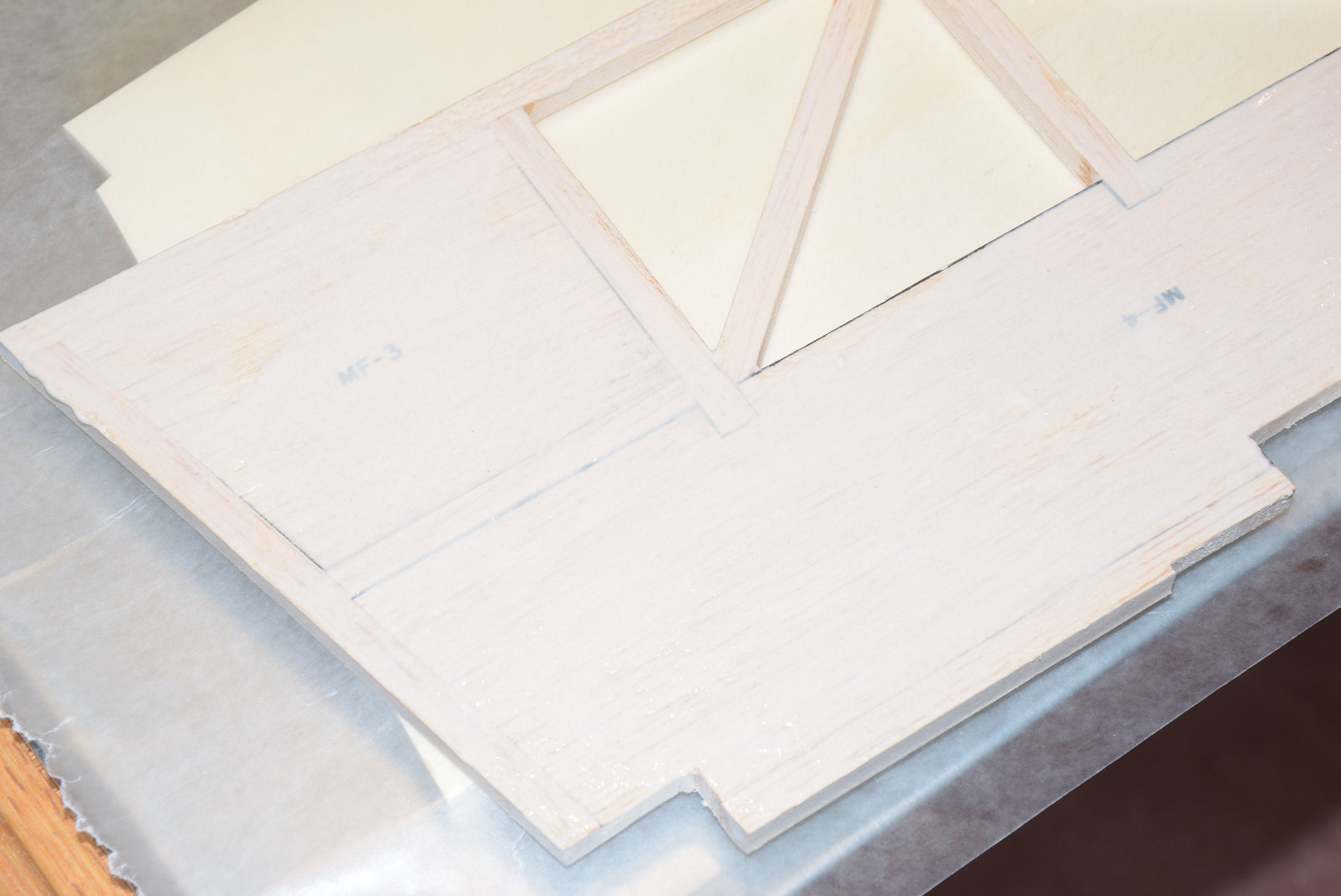
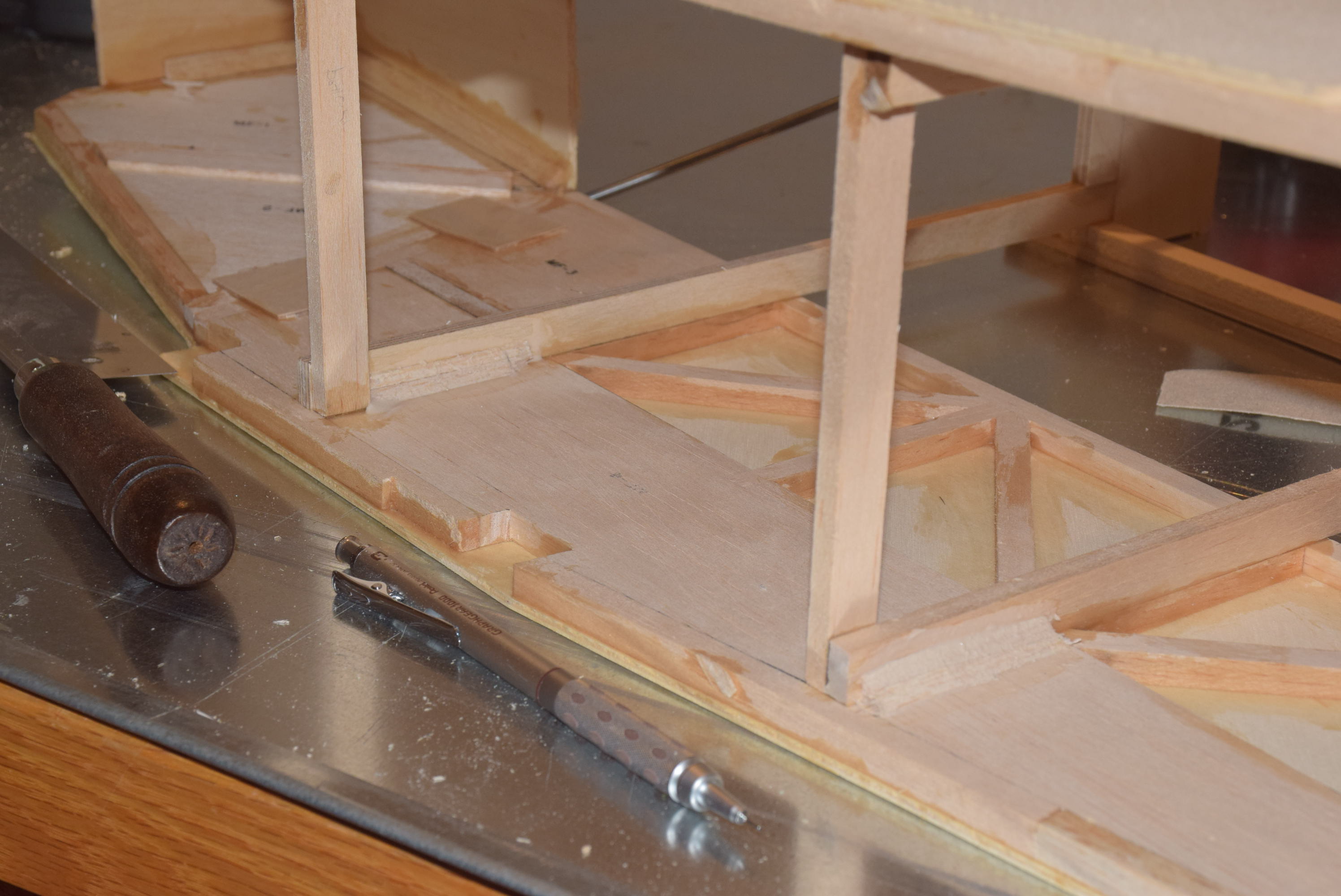
With both fuselage sides full dry, it’s now time to begin gluing in the formers. If you took your time to build the fuselage sides very accurately, they should come out to be nearly identical in overall dimension. If not, sand them so they are equal as much as possible.
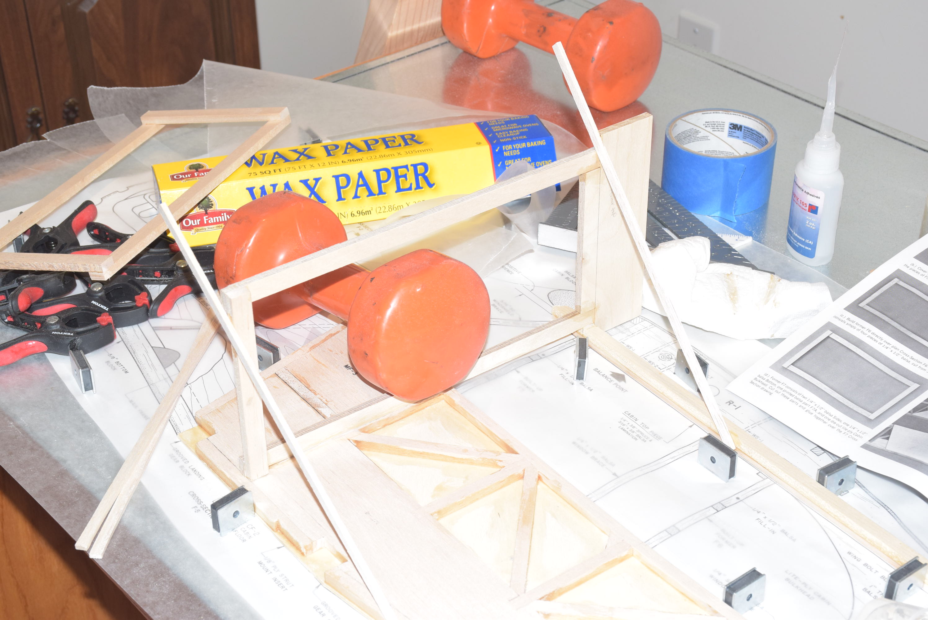
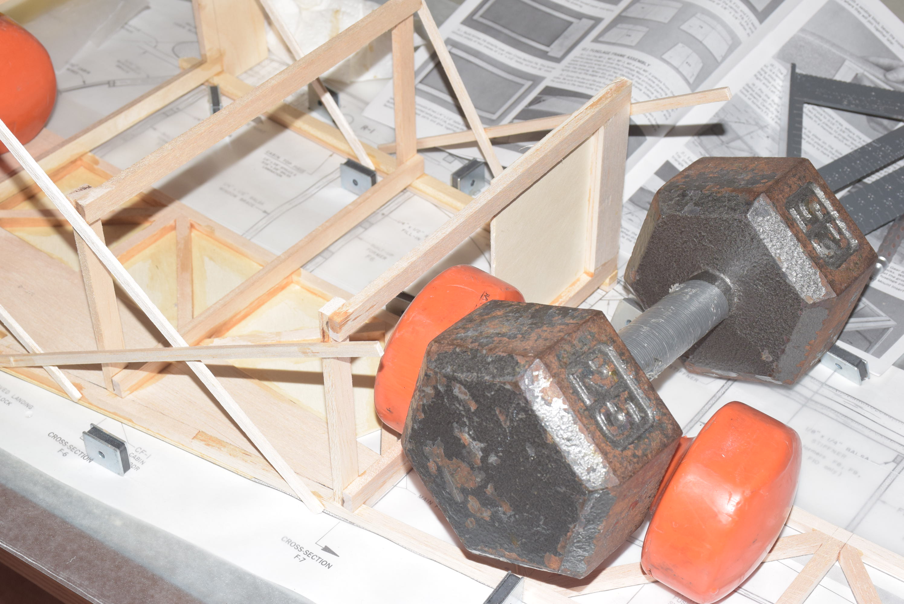
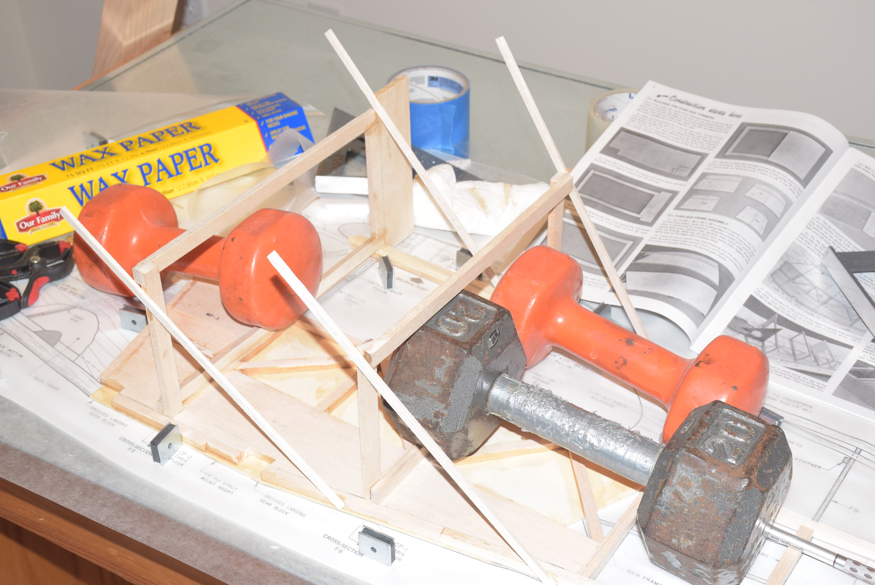
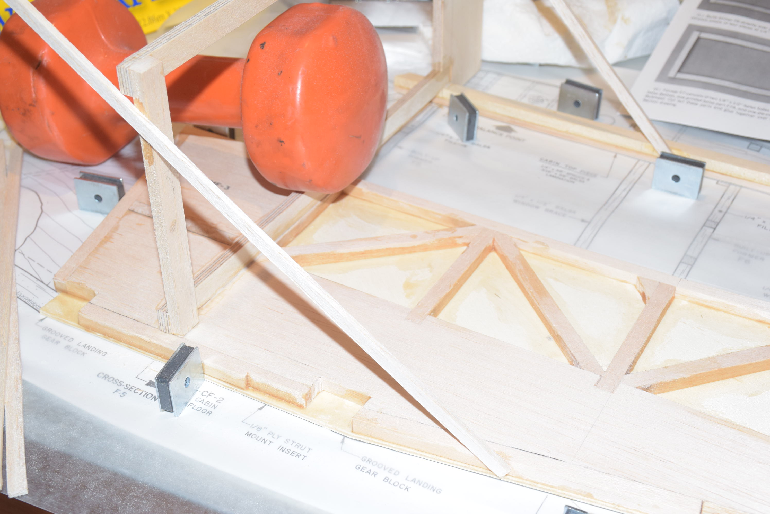
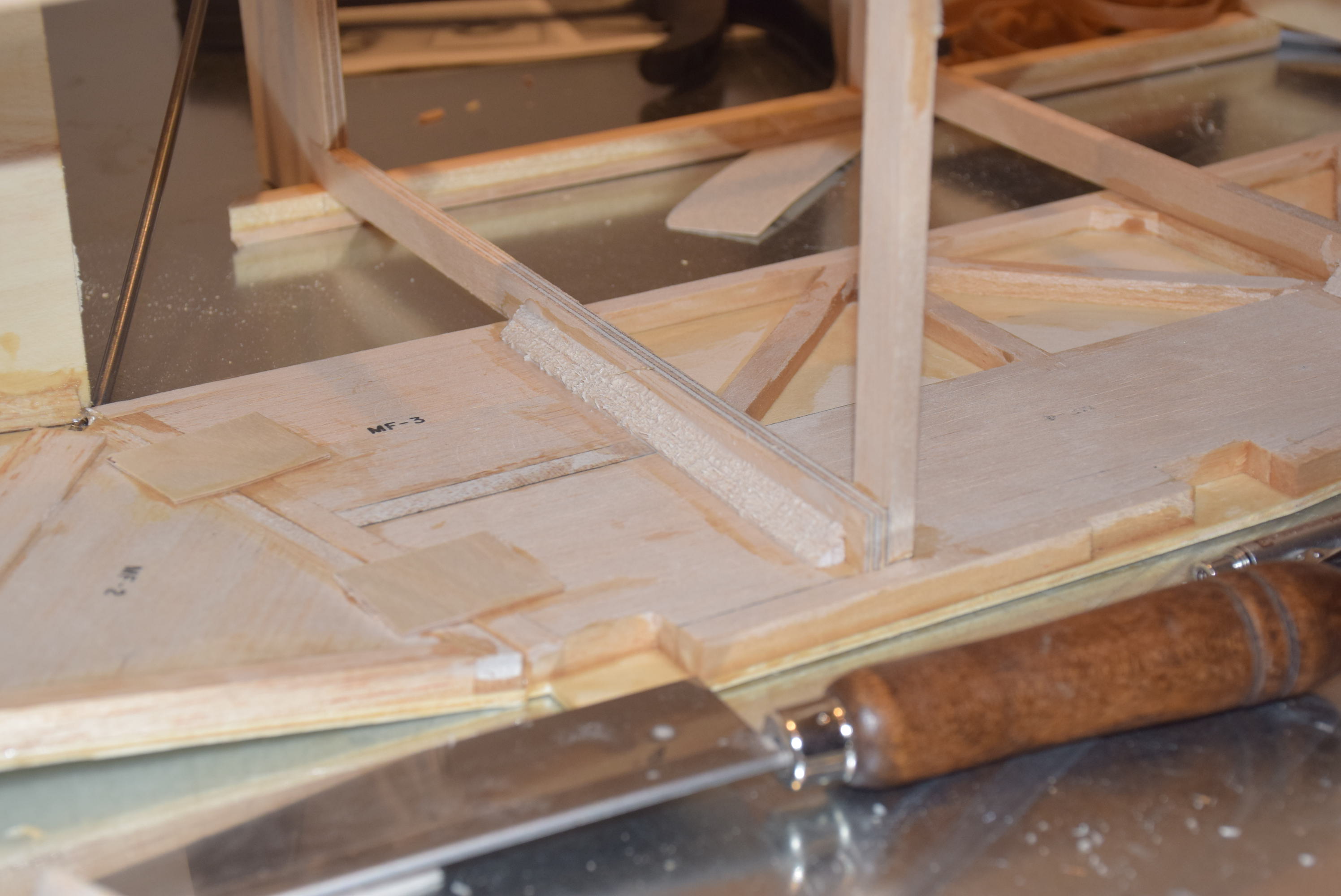
Begin with placing the right fuselage side over the plans and measure where the formers should be glued. Drawing lines with a straight edge will help for lining them up when gluing them in place. Glue the formers to the right half using epoxy or wood glue. Use a square to make sure they dry perpendicular to the fuse side. I cut small strips if 1/8 balsa and used them as a brace to hold the former in place while the glue set. I also added weight as shown in the photo to ensure a very strong joint. With all three of the main formers in place, allow them to dry over night. Gluing on the left side of the fuselage can be a little tricky. I transferred the lines from the right fuselage side to the left to help use that as a guide. See the photo below for how to use two triangle squares to accurately line up the front of the left fuselage side with the right side. Also, this is one place where you can trust your eye – if everything looks good and it seems to measure up, then everything is most likely aligned. Once all is dry, I added some additional triangle balsa as shown below.
In Part 5 we will take a look at joining the rear halves of the fuselage together and how to make sure you fuselage is perfectly square!