Author Archives: webmaster

ZMR 250 4S Conversion – Basic Betaflight Setup

Category : FPV

In part 2 of the ZMR 250 4S conversion build series we’ll take a look at migrating from Cleanflight to Betaflight with the NAZE 32 F1 Revision 5 board. This tutorial will also serve as a guide to those who may be setting up Betaflight from the get-go!

We’ll cover the following steps:

  • Flashing Cleanflight to NAZE 32 board
  • Basic settings using Betaflight Configurator
  • Taranis D4R-II Receiver setup using CPPM

The purpose if this tutorial is intended to be very basic in order to get you in the air quickly and not get bogged down with complex setups.  Let’s get started.

Flashing Betaflight to NAZE 32 Board
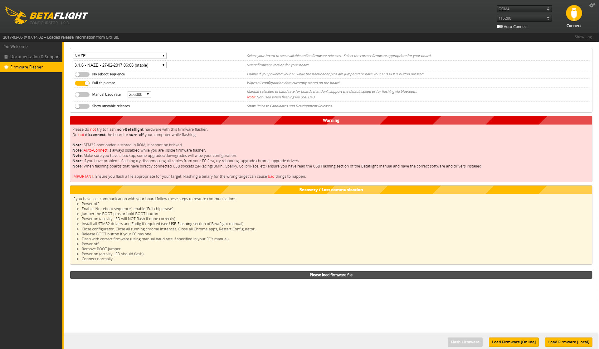
If you haven’t already, be sure to download the Betaflight configurator extension from the Chrome store.  Connect your board with a USB cable and launch the Betaflight Configurator.  Click on the “Firmware Flasher” tab on the main screen.  Choose your board from the dropdown menu  and choose the most recent version of the Betaflight release from the firmware dropdown menu.

The only other setting on this screen that should be changed is to enable “Full Chip Erase” so we can start from a clean slate.


Basic Setup Using Betaflight Configurator
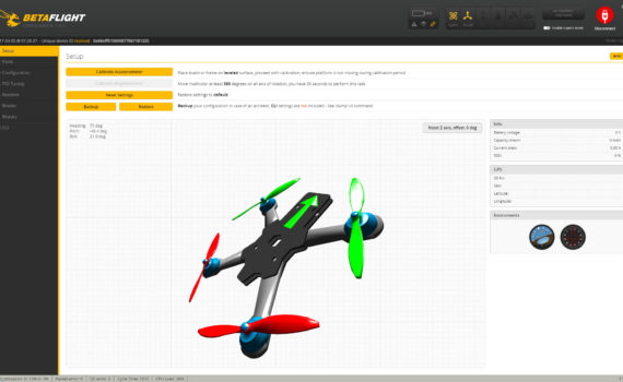
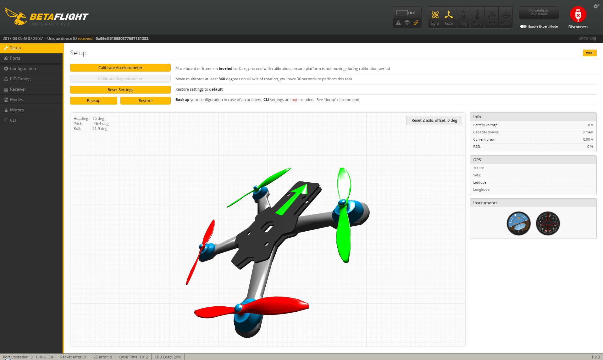
Once the Betaflight firmware has been flashed to the board it will reboot.  Click the “Connect” button in the upper right of your screen which will take you directly to the main “Setup” tab.  On the setup screen you will see a graphic of your quadcopter showing it’s orientation.  Move the quad copter around making sure each axis is moving the correct direction.  For example, if you roll your quadcopter to the right, it should roll to the right on the screen.  Check each axis: roll, pitch, and yaw.

If a particular axis is NOT moving in the proper direction, follow these steps:

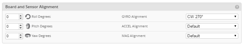
  1. Click on the configuration tab
  2. Scroll down to the “board alignment” section.
  3. Only change one axis at a time – using the dropdowns to the right to adjust the board in the desired direction.  Once you make a change click on the SAVE AND REBOOT button on the lower right of the screen.
  4. Go back to the setup tab and check each axis again for proper movement.
  5. Repeat as needed until each axis is oriented correctly.
  6. Adjust only one axis at a time until that is set properly.

Now that the board is aligned properly, move on to the Configuration Tab (we’ll come back to the ports tab in a later tutorial once we setup telemetry with the D4R-II Receiver).

Here are the basic settings you need to check and set properly for your particular quadcopter.

  • Mixer – Choose quad type (Default is quad x shape)
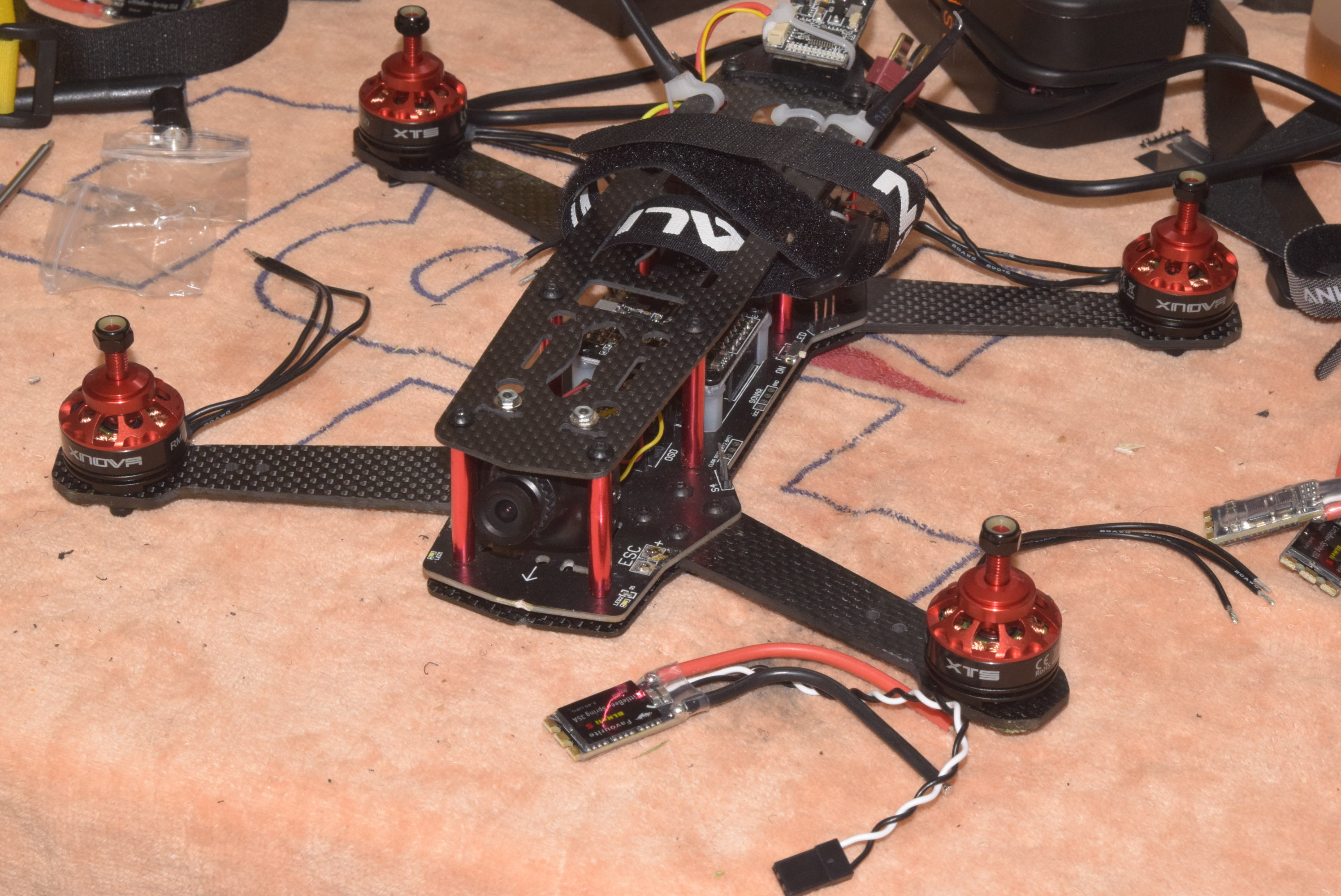
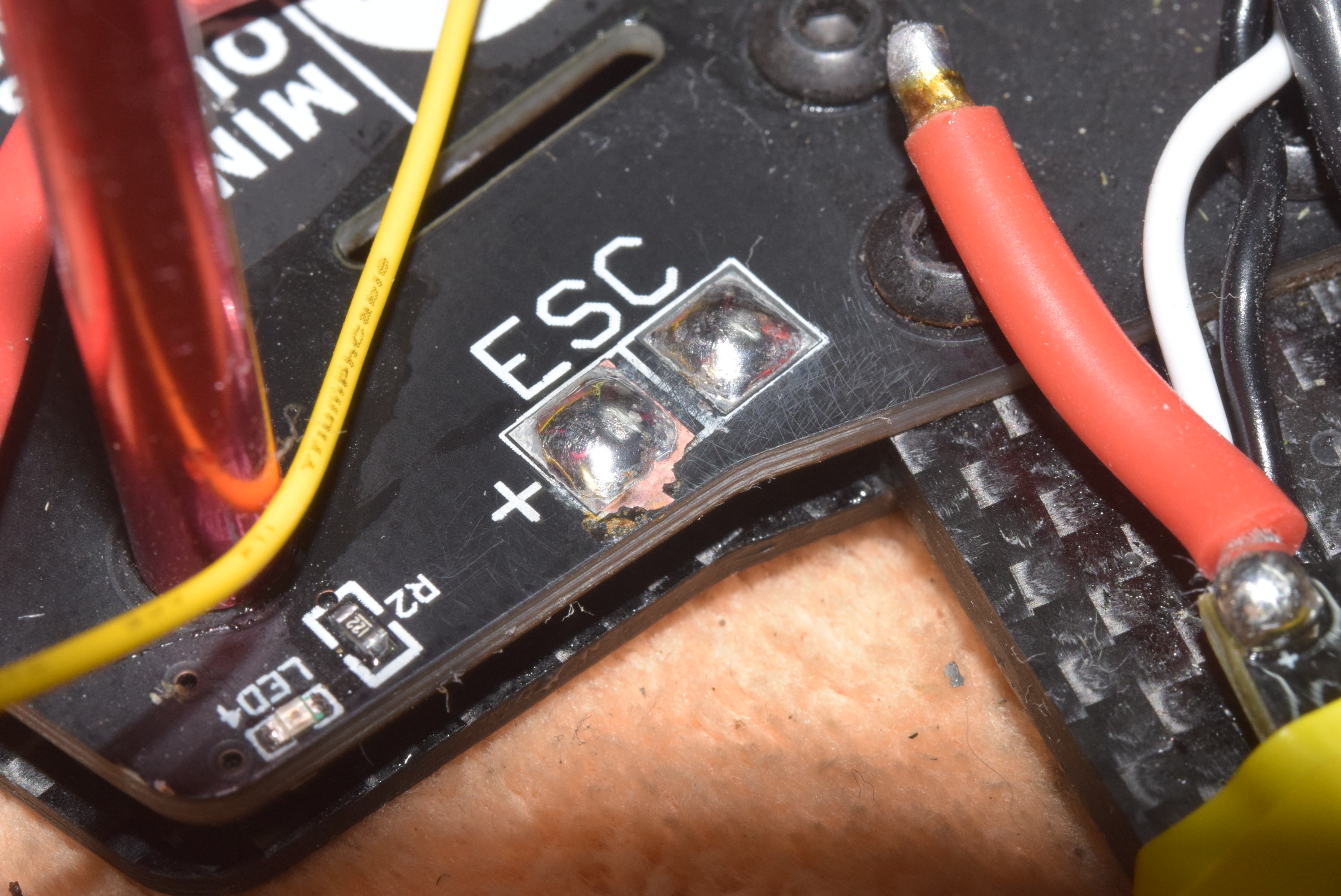
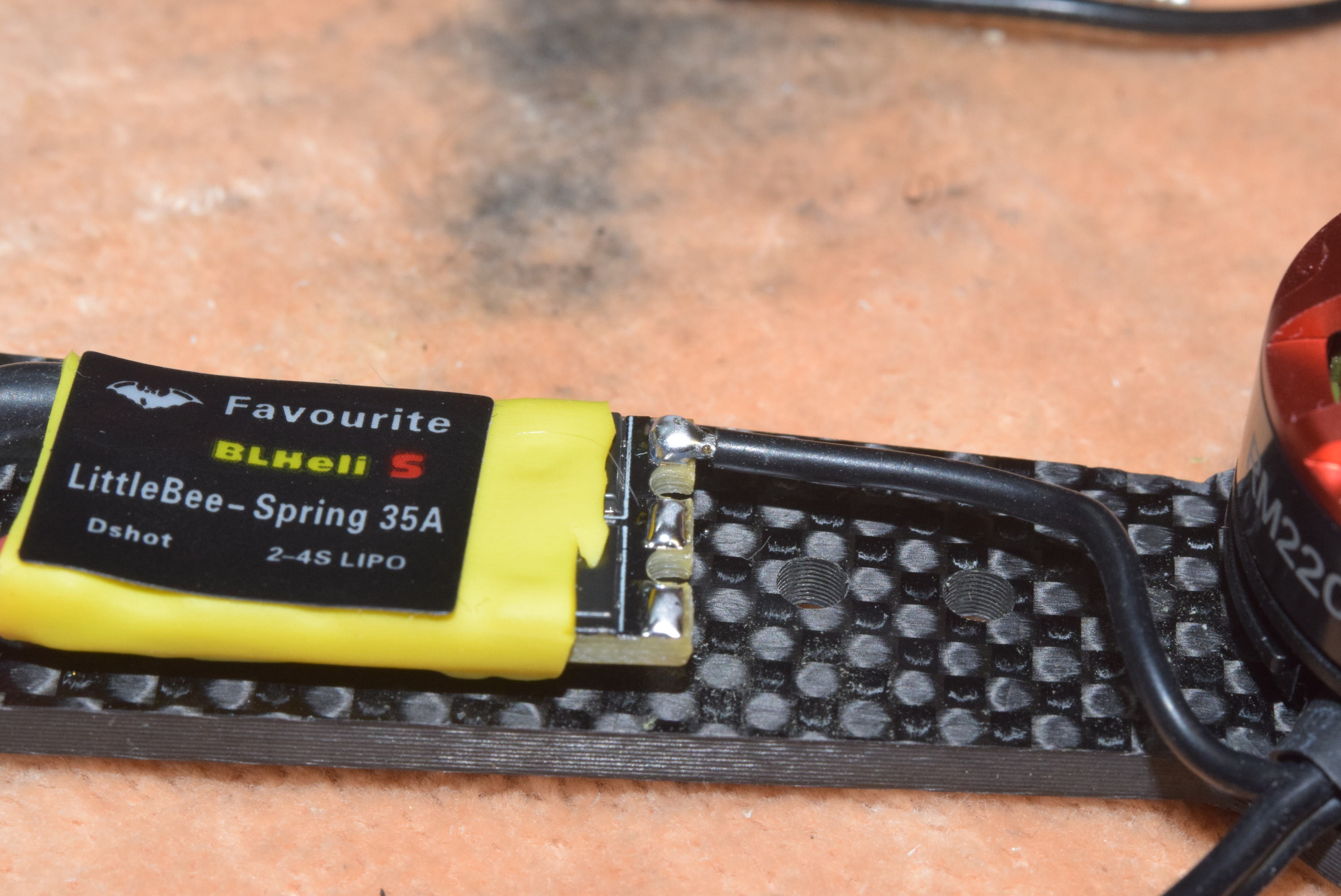
  • ESC/Motor Features – Set ESC protocol based on your particular ESC, for this example we’ll use MULTISHOT for the LittleBee 35 amp BLHeli_S ESC’s we are using.
  • Min and Max throttle – I like to set min to be a min of 1000 and a max of 2000
  • Minimum command ( you can leave this as default or change it to match the min throttle setting if you don’t want your props to spool up slightly when armed.)
  • Receiver – Set this to match your Receiver, for this particular quad I’ll set it to PPM RX Input – since we will be using CPPM on the D4R-II Receiver.
  • All other settings on this tab can remain as default for now.
  • SAVE AND REBOOT!

Quadcopter should now be responding to Inputs from your transmitter.
With those basic settings in place, we can move on to the Receiver tab to make sure we are seeing the inputs from the correct channels.  The following assumes you have already bound the receiver to your radio.

Move the sticks around on your transmitter to make sure pitch, roll, and yaw are all on the proper channels.  For the Taranis FrSky Transmitter your channel mapping should be: TAER1234.  You can choose this from the dropdown or manually type it in.

I also like to setup an arming switch on my radio right away, otherwise you have to hold full left yaw and zero throttle to arm and disarm.  Having it on a switch will allow you to instantly dis-arm the quad in case of a crash!

To setup an arming switch on the Taranis X9d Plus, follow these steps.


  1. From the main screen press MENU once
  2. Then Press PAGE until you get to the INPUTS screen (5/12)
  3. Press the – (minus) button on the right of the transmitter until you highlight the next available empty input – (in most cases it should be right after the rudder input on this screen).
  4. Press Enter Once to enter the setup area for this new input.
  5. Set the SOURCE to be the switch you want to use.
    1. use the – (minus) key to highlight the SOURCE area and press ENTER once.
    2. Then simply toggle the switch up and down you wish to use… it will then record this as the input you want to use.
    3. Press exit until you are back to the Input screen.
  6. Next, press PAGE once more to advance to the MIXER screen.
  7. Use the – (minus) button to navigate down to the next open channel – usually this will be CH5. Press enter once.
  8. Go to the “SOURCE” area once again and choose either the switch name or the name of the input if you named it on the INPUTS screen.
  9. Press EXIT until you are back at the main MIXER screen.

You should now see the switch show up as AUX 1 in the Betaflight configurator. You may have to connect your flight battery to power the Receiver – MAKE SURE THE PROPS ARE REMOVED!!!

Add additional switches as needed.  For CPPM on the D4R-II Receiver they recommended NOT using MORE than 6 channels.

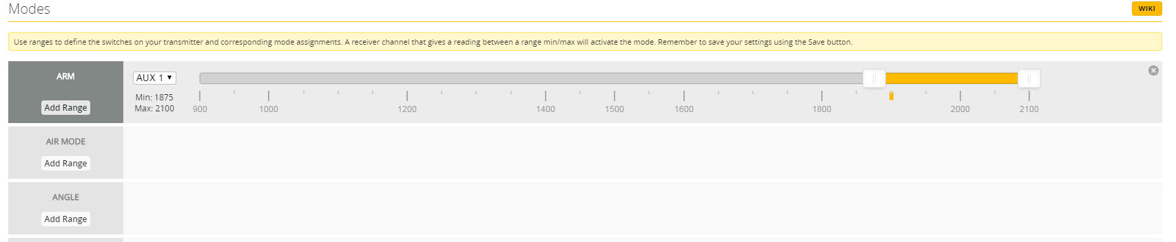
Finally we will move on to the Modes tab in the Betaflight configurator.  We’ll use this new switch we setup to Arm the quadcopter for flight.

With the receiver inputs all moving the proper way, we can adjust the ARM sliders to be activated when the arm switch is flipped up or down.  In this particular case with the ZMR 250 I set the ARM mode to activate when the switch is in the UP position. Adjust the sliders so they cover where the little yellow tick as shown.

SAVE AND REBOOT!

In Part 3 we’ll take a look at setting up failsafe using the Taranis D4R-II Rreceiver.


ZMR 250 3S to 4S Conversion – Motor and ESC Upgrade

Category : FPV

In part 1 of the ZMR 250 3S to 4S conversion we will be upgrading the motors from DYS 1806 2300KV motors to the more powerfull 2204 2300KV XNOVA motors. Migrating from 3S to 4S packs will also require an ESC upgrade so we are going to be installing the Favourite Little Bee 35 amp ESC’s.

XNOVA 2204 2300KV Motor Specs:

  • 3S – 4S compatible
  • 5mm Prop Adapters included with locking nuts for each
  • two sizes of motor mounting screws included with package to accommodate different arm thickness
  • 2300KV
  • Precision balanced and hand wound
  • some cool decals!


Favourite FVT LittleBee Spring 35A BlheliS Specs:

  • 2S-4S Compatible
  • Blheli_S Firmware (with Blheli bootloader)
  • Able to upgrade firmware through Cleanflight/Baseflight pass-through
  • 35 amp continus with 40 amp burst
  • Supports:
    • Damped mode
    • Oneshot125
    • Oneshot42
    • Multshot
    • Dshot – (if supported by Flight Controller)

Let’s get started!

First we will start by installing the included 5mm prop adapters using the supplied hardware.  Make sure to use some thread locker here as we don’t want these things flying off!


Once the motors are prepped I like to install them on the quadcopter right away.  This will make things easier when we solder the ESC’s in place later since we can trim the wires to fit exactly.

NOTE: with the ZMR 250 arms and the 2204 motors the wires aren’t positioned directly over the center of the arm so I made sure to point that toward the back of the copter.

With the motors installed we can turn our attention to the ESC’s and getting those installed.  As you can probably tell from the photo above there is a lot of extra wire that we will cut down so everything fits nice and tight to the frame!  Start by removing the shrink wrap around the ESC so we can remove the signal and ground wires (small white and black wires) from the ESC and trim these to size. 

Once the signal and ground wires are shortened to the desired length, place them on the quadcopter are in there intended position and secure temporarily with some electrical tape. With the ESC in it’s desired location we can then solder the main power wires to the PDB board on the ZMR 250.

If your ESC connections are a little tarnished or diry you can clean them with a bristhl brush and a little window cleaner!

Before…

After… nice and clean!


With the ESC’s installed on all four quadcopter arms you can start to wire the motors in one by one.  Also when wiring up the ESC’s and motors this can be a time consuming and tedious process so make sure not to be in a hurry here! Since I removed the factory shrink wrap you can replace it with a color of your choice and re-attach the original label.  I also like to place a small piece of double sided tape under each ESC and between the arm then secure with a zip tie as shown in the photo below.  One added benefit of of the securing with a zip tie in this position is that it gives the quadcopter some “landing legs” of sorts!

In part 2 we’ll take a look at migrating the original F1 NAZE 32 from Cleanflight to Betaflight!


Sig J-3 1/4 Scale Cub Build Series – Part 13 – Finishing and Covering.

Category : Uncategorized

With the wings completed in part 13 of the Sig 1/4 Scale build series, we were left with an air frame that is now ready to be covered!

For this build, I opted to go with a color scheme other than yellow!  I know, I can’t believe it either!  Part of the reason for not sticking with the traditional Cub yellow color scheme was to avoid confusion in the air with the other yellow cubs in our club!

I decided on a rather simple three color scheme of bright red, white, and some gray for an accent color.  I covered the plane using the Hobbyking branded covering and I was quite pleased with how easy it was to work with and how well it formed around curved surfaces!

Another benefit of the hobby king covering is standard rolls around roughly 5 (15 feet) meters long and around $10 a roll!

https://hobbyking.com/en_us/hardware-accessories-1/covering-film.html

Just a couple of quick tips when applying covering film:

  • Start with the “bottoms”; this includes covering the bottom of the wings first, bottom of the fuselage, then work your way up to cover the sides and finally the top.
  • Use razor blades for cutting the excess covering instead of xacto blades as these blades seem a little thinner and sharper!
  • If you are overlapping colors, make sure the overlap is at least a 1/4 inch over the first color and preferably over a fully sheeted area.  This will ensure a nice tight seal.
  • Also keep in mind any overlap seams in relation to air flow.  You will want the leading edge of a wing to “overlap” the first color.  This prevents the airflow from eventually working the seam loose.

Electronics Used:

  • Futaba 6 channel RX
  • two 2-cell LiPo 2600 MAH (make sure your servos and RX are rated for 7.4 2S voltage)
  • Hitec HS5665MH Servos for control surfaces
  • Dubro Large Scale pull-pull rudder system.
  • Hitec Large Servo Horns.
  • Dubro 4-40 clevis and rods
  • Great Planes large scale control horns.
  • 2 Switches in combination with 2 cell LiPos above.  Each power system is separate.  One for the RX and servos, and one for the DLE 40 ignition.
  • Dubro 20oz Fuel Tank


Here are a handful of photos of the finished product. The clear windows were added after the maiden flight!  I’ve also included a few photos of the electronics setup for this plane as well.

A few parting notes:
You’ll notice the 20 oz gas tank is more centrally located as close to the CG as possible.  Sig recommends the tank be put far forward in the nose.  With the heavier DLE 40 engine this isn’t necessary. In fact, once all the electronics were in place, it was just a matter of moving the 2 RX packs around to locate the perfect CG!  I couldn’t believe how well it worked out!

Also the elevator servo is mounted in the rear of the plane instead of running a long control rod.  Take some precautions to seal this servo from water or use a water proof servo here.


Tower Hobbies Ultimate Bipe GP/EP ARF – Build and Flight Review.

The Ultimate Bipe from Tower Hobbies is certain to turn heads with it’s bright red and yellow color scheme!

Early in the flight season this year I was certain I wanted to add a biplane to my ever growing fleet of radio controlled planes.  When I saw that Tower Hobbies was going to release an Ultimate Bipe in a 45″ wing span I was certainly interested.  Having had good experience with Tower Products in the past (Kaos 40) I was certain this would also be a quality product – and deliver a quality product they did!

I decided to purchase the kit after Tower Hobbies had this particular ARF on sale.  I decided to outfit the plane with their  recommended equipment:  Rimefire 55 Motor, 16×6 or 16×8 prop, Castle Creations ESC, and the Tactic TS25 Servos.

dsc_8021

The ARF arrived packaged very well and every part was wrapped in the usual plastic bags secured with tape in the shipping container.  I removed each part one by one and inspected it by hand looking for any defects or broken pieces.  Everything looked perfect.  The covering was done very well and only a minor wrinkle here or there was found.

dsc_8020

The Tower Hobbies Ultimate Bipe comes with an easy to follow and heavily illustrated instruction manual.  Starting with the wings, you have the option to use either two or four servos for the ailerons in the wings.  I opted to go the four servo route (for my particular setup I used an eight channel receiver) since my radio allows me to setup the necessary mix to operate this many servos each on their own channel.

If you are using four servos, the manual provides directions on where to cut the covering on the top wing to allow you to install the additional servos.  The kit also includes two extra servo mounting plates for this purpose.  The kit also came with enough hardwood servo mounting blocks for the extra servos.  I cut the blocks down slightly for a better fit and then one by one mounted them to their plates using thick CA.  I drew a reference line with a pencil to help ensure accurate positioning of the servos.  This is a tedious step so it is best not to rush this process!

Once the servos are mounted, the servo wires and any extensions you’ll need can be routed through the wing with the provided guide string already built into the wing from the factory.  (NOTE: In the photos it shows I used a servo extension, later I removed these extensions in favor of a direct solder connection… to help reduce any possible fail points within the wire.)

With the servos completed and installed in the wings, mount the bottom wing to fuselage. The bottom wing is used for alignment of the horizontal stabilizer.  Fitting the stabilizer requires centering it left to right and making sure it’s parallel to the bottom wing.  Follow the direction in the manual to align the stabilizer front to back. Only minor sanding should be required to get the alignment perfect.  Once that is in place I used 30 minute epoxy to secure it to the fuse. Don’t forget the elevator joiner wire should be put in place at this  time as well!

dsc_8044

Next, the vertical stab is installed in the pre-cut slot provided in the fuselage. Use 30 minute epoxy and secure in place while it dries.

Another nice touch with this ARF kit, is that the ailerons come pre-glued to the wing and the hinge slots are already cut for the elevator and rudder!

 Once the horizontal and vertical stabilizers are in place, you can install the elevator and rudder control surfaces using the provide CA hinges. With the pre-cut hinge slots everything should fit together nicely!

At this point, the build really starts to progress quickly!  With all of the control surfaces glued in place you are now ready to install the motor and ESC.  In the back of the manual they provide a drilling template for the Rimfire 55 motor and instructions on where to mount the Castle Creations 75 amp ESC to the motor box.  For the ESC you’ll have to make a battery lead extension.  I added a few inches to the recommended length in the manual to make connecting the battery a little easier to handle.

Another nice touch with the Tower Hobbies Ultimate Bipe is the battery mounting plate included with the kit.  This battery plate bolts in place with a single 1/4-20 bolt and blind nut. This makes battery changes and getting the CG in the same place during battery changes much easier!  Tower certainly receives an A+ for that handy little feature!

dsc_8080

Next, you can begin mounting the servos for the rudder and elevator.  Controls rods are provided with the kit.  You’ll have to locate the exit holes and make a small slit in the covering for the control rod exits.  Be sure to consult the manual for which side is for the elevator and which side is for the rudder since they are in slightly different locations. While mounting the rudder and elevator servos you will be working on the plane upside down.  (NOTE in the manual they include an addendum instructing you to install some filler wood strips because the servo slots are a little too wide.)

Wood filler strips and mounting plate for RX

Wood filler strips and mounting plate for RX

 With all the servos in place you can now install the servo control horns if you have not already done so.  There is a hard ply mounting location for the control horns in each aileron which I was pleasantly surprised to see! Harden the screw holes with thin CA.

With the plane nearly finished at this point I moved on to mounting the canopy.  One thing I didn’t like about the canopy was the noticeable gap at the front where it mounted to the removable hatch.  I created a paper template and used some of the extra covering included to seal the edge around the canopy.  See photos below for details.

Mounting the Cowl:
Tower included several hardwood mounting blocks for the cowl.  Align the cowl to provide enough clearance for the spinner back plate if using one.  I also like to visually align the cowl to make sure it is centered left and right and up and down while looking down the propeller shaft.  Once satisfied with the alignment, secure the cowl in place with blue painters tape and begin to drill holes for the mounting screws one by one.

That’s pretty much it!  This was one of the quickest ARF builds I’ve done and was easily accomplished in a few evenings!

 Just a few additional notes:
Plan on using a fairly large battery for this Ultimate Bipe as you will need the extra nose weight in order to achieve correct CG.  I’m getting seven minutes of flight time on a 4500 mah 6S pack with a lot of sport flying and several full throttle bursts!

I setup my control throws using the low rates in the manual for the maiden flight.  However, even the low rates on ailerons felt way to responsive.  I found my self cutting those back to around 1/4 to 3/8 of an inch of throw up and down.  I dialed in around 30% expo for the maiden flight as well.

One issues to note with the landing gear is that the landing gear studs do not appear to be long enough to allow the nylon lock nut to fully tighten.  I used blue thread lock to remedy that situation.

Nylon locking nut does not fully tighten.

Nylon locking nut does not fully tighten.

The Rimfire 55 motor provides plenty of thrust and vertical power using a Xoar 16×6 prop.  In the manual they recommend a 16×8 for ultimate (pun intended) performance.  I’ve pushed the plane pretty hard with the 16×6 prop and the motor hardly reaches above room temperature.  The Tower Hobbies Ultimate Bipe had plenty of air flow and is also aided by the spinner I’m using from Gator RC. NOTE: the motor mounting template appears to show the motor mounted off center – this is normal as it accounts for the amount of right thrust built into the firewall.

Finally, I decided to use the Castle Creations 10 amp BEC since I was powering six digital servos.


Flight Review
The main purpose of this article was to focus more on the build aspects of the plane but I do want to share a few notes about it’s flight characteristics.  The Tower Hobbies Ultimate Bipe will easily lift off the run way at a little above half throttle.  This particular plane can be flown nice and easy or full on 3D if you wish!  It will handle anything you can throw at it.  It seems to roll as if it’s on a string – staying precisely in it’s track and responding only to your inputs.

When setting up the CG location at home before your first flight be sure to not make it excessively nose heavy as you will end up having to dial in so much up elevator.  The Tower Hobbies Ultimate Bipe tends to like it CG location to be where the fuselage is level with the ground.  With the CG correct it should take very little elevator to maintain level inverted flight.

Landing the Ultimate Bipe is also a pleasure.  You are able to ease it in with a little throttle and gently set it down with a slight nose up attitude to bleed of some of the air speed on final approach.

Knife edge flight did not produce any coupling or any unwanted characteristics.

Overall the Ultimate Bipe is a clear winner from Tower Hobbies!

Equipment Used:

  • Rimefire .55 Brushless Motor
  • Tactic TS25 Digital Mini Servos (6 or 7 needed with glow)
  • Futaba R2008SB 8 Channel RX
  • Pulse 4500mah 6S 45C LiPo
  • Castle Creations 75 amp Edge ESC
  • Castle Creations 10 amp BEC
  • Xoar 16×6 Beachwood Prop (the Xoar prop was a direct fit with the included prop adapter with the Rimefire .55 motor – no prop reaming required)
  • Gator RC Electric Spinner – size based on preference.
  • Deans plugs for battery connections.

Some Additional Photos


Sig J-3 1/4 Scale Cub Build Series – Part 12 – Wings and Wing Tube

Since the Sig Quarter Scale cub is an older kit I decided I wanted to “modernize” the wing design by incorporating a bolt on fuselage center section, wing tube, and a two piece removable wing. The original design called for the center section to be permanently attached to one of the wing halves. I did preserve the functional wing struts for this build however.

To begin the wing design I had the plans scanned at my local UPS store so I could work off an image of the plans using a program called DevWing. Many builders in this hobby are familiar with the “Profili” program offered by the same company. https://www.devcad.com/eng/devwing.asp

DevWing is a great program that allows you to completely design a wing with spars, wing tubes, dihedral, servo boxes, and even multi-part wings just to name a few of the features! I started by basing the design off of the scanned sig plans and drew in the positions for the aileron and spar locations. I also used some basic trigonometry to build in 1.75 degrees of dihedral into the wing. (A little dihedral in a cub is a good thing giving stable flight characteristics and also prevents the wing from looking like it’s “drooping” in flight compared to a completely straight wing with no dihedral.)

DevWing also allowed me to specify the wing tube locations and it automatically accounts for the dihedral I had specified. I decided to make the first three ribs incorporate a wing tube from TNT Landing Gear. I used their 5/8″ by 30″ long aluminum tube with a .049 wall thickness and socket.

Another thing I decided to do was build in two degrees of washout into the wings. DevWing allows you to configure this and builds the washout into the building tabs it creates for each rib. This allows you to build the wing on a flat surface without the need for a wing jig! Washout will prevent the wing tips from stalling as quickly as the center of the wing toward the fuselage – helping to reduce the chance for the dreaded tip stall. (NOTE: the test flights with this built into the wing have been extremely stable and without event. Landings and take offs are very graceful and smooth!)

DevWing also allows you to lighten the ribs by automatically generating cutouts into the ribs. This really helps to keep the weight down and doesn’t compromise strength. It also serves to make running servo wires much easier. With the DevWing program you have complete control on how much material the program is allowed to remove. I used 3/16 balsa – which is a little thicker than stock. Using the thicker ribs will make up for an deficit in strength and wider balsa is easier to work with while building the wing on the bench!

Once the wing is fully designed (you can preview a 3D view of the wing from any angle as you build so you can get a good idea of what is looking like) DevWing provides an export feature allowing you to take your parts to the nearest CNC machine for cutting. (A couple of years ago I invested in one of the eBay CNC machines – so far it’s been reliable and has worked really well! You’ll have a lot of fun with all the precise parts you can make!)

Once all the parts were cut out I began the building process on my magnetic work bench. I’ll spare you the detailed description of building the wings since the process is the same for most wings. Just remember that the flatness and straightness of the building surface will determine how straight and precise your wings are.

I normally start by laying down the bottoms spars in place and securing them with magnets to keep them from shifting around. Next I start by placing the ribs in one by one – dry fitting them to ensure a good fit before any glue is added. Once the ribs are in place I’ll glue them with CA making sure to use a square next to each one to make sure it’s perpendicular to the spar and lines up properly on the plans. With the ribs securely in place I’ll put on the leading and trailing edges. Finally I top things off with the top spars. Once that is all dry I then add in the shear webbing which greatly increase the strength of the wing at this point. Once the spar webbing is dry I sheet the top and bottom using the traditional D-tube construction method. Once the sheeting is in place the wing is very stiff and strong – just the way we want it!

Here’s a gallery of photos of the building process!

I will write a separate post showing some screenshots from the DevWing Program.


Have a question or comment?

If you have a question or comment, please feel free to email us at the following address: [email protected]

Other Information