Sig J-3 1/4 Scale Cub Build Series – Part 11 – Cutting Cowl for DLE 40 Twin
Category : Model Airplane Building
In part 11 of the Sig J-3 Cub Build series we will take a look at cutting out the cowl for the DLE 40 twin. (NOTE: At this point, the cub is actually finished and has already had it’s maiden flight both off land and water! The DLE 40 Twin Engine is a great match for a 25% size J-3 Cub – balancing out the plane out perfectly!)
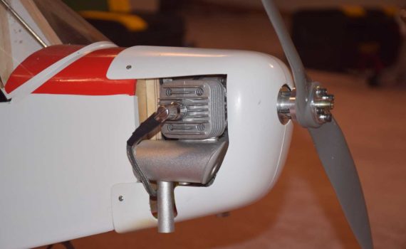
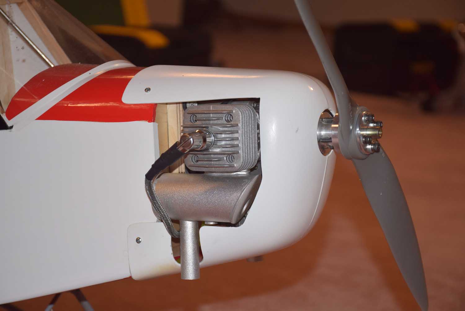
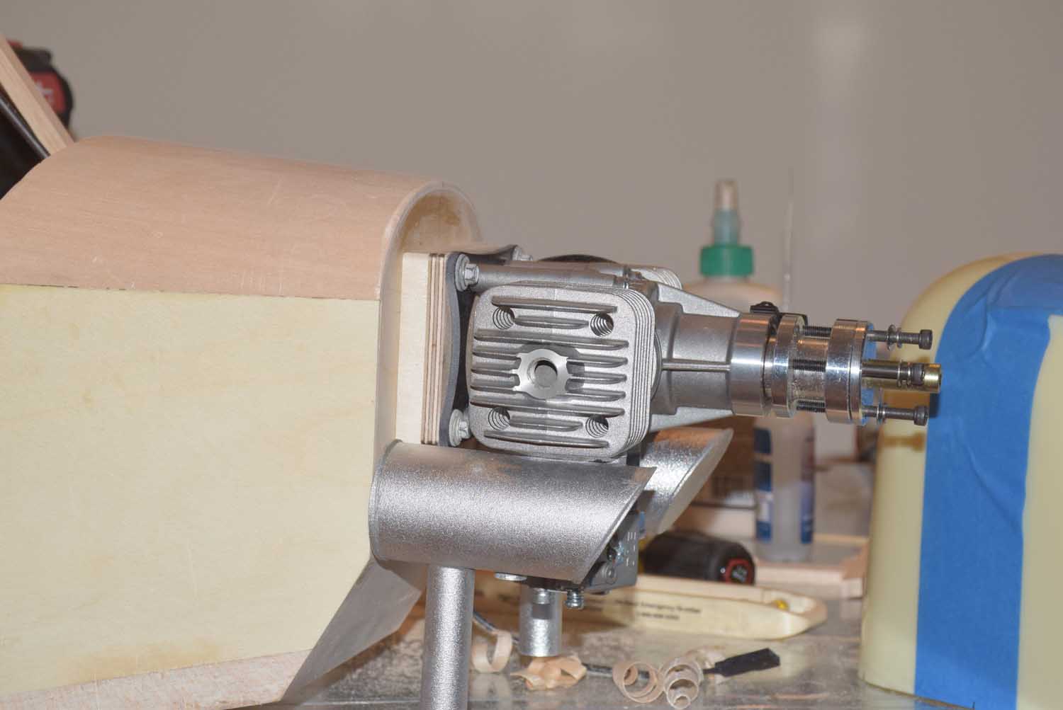
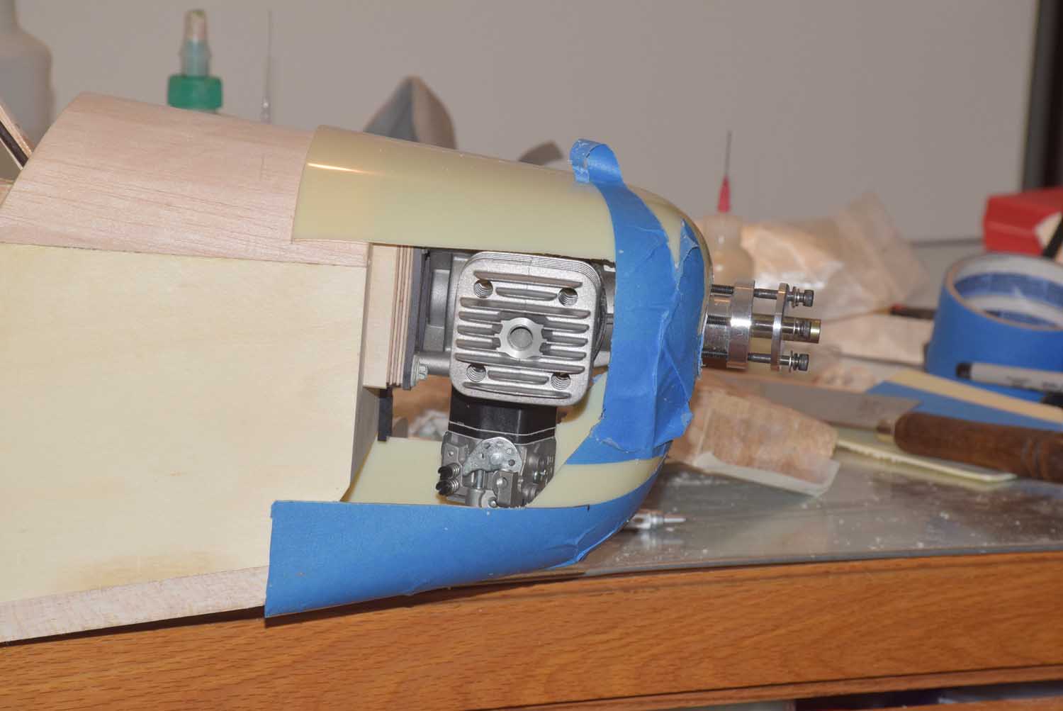
The DLE 40 engine is a larger engine and will require you to cut out a significant portion of the cowl on each side. Also note that the cylinders are offset from one another so you will need to measure and mark out each side as needed.
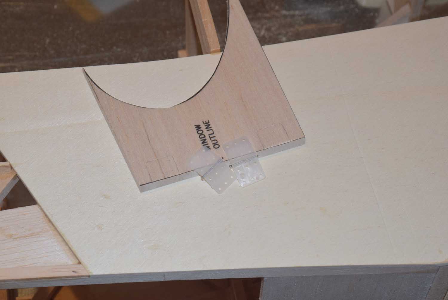
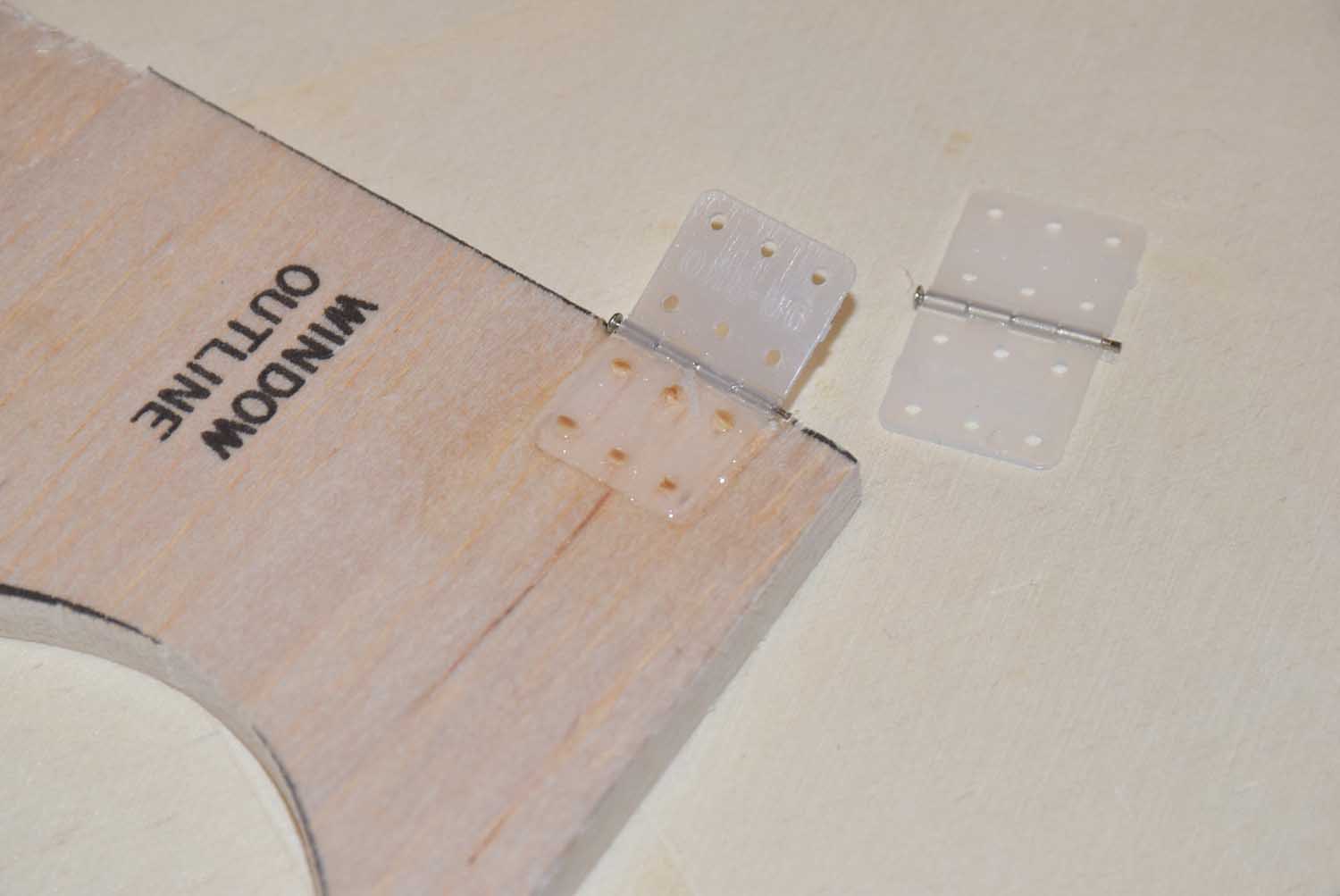
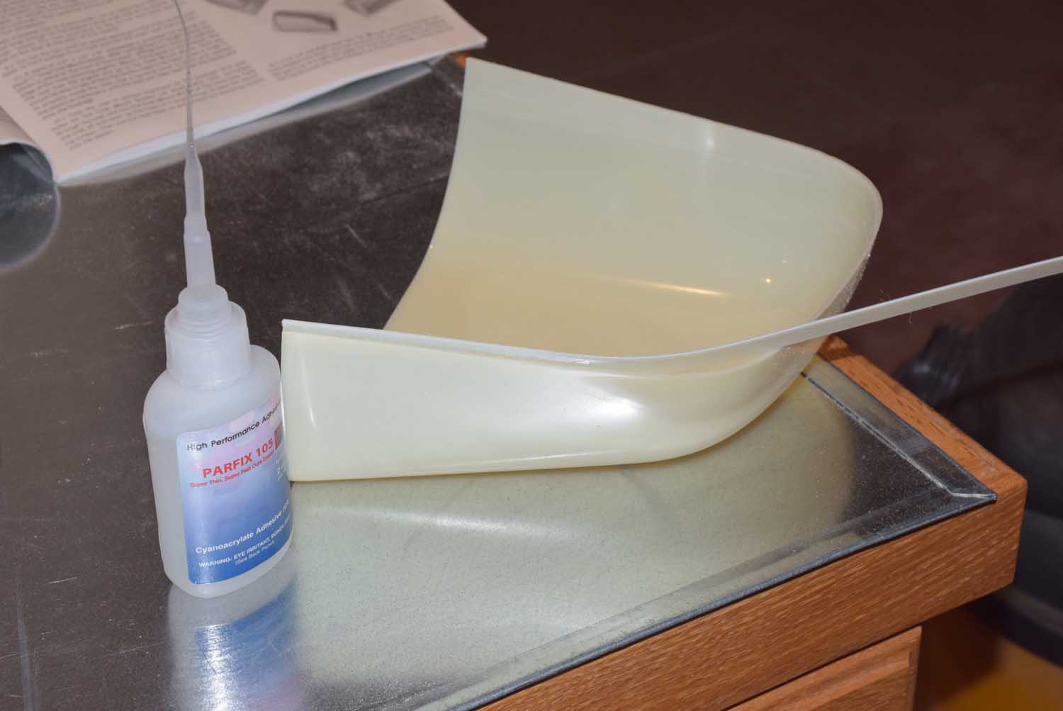
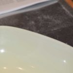
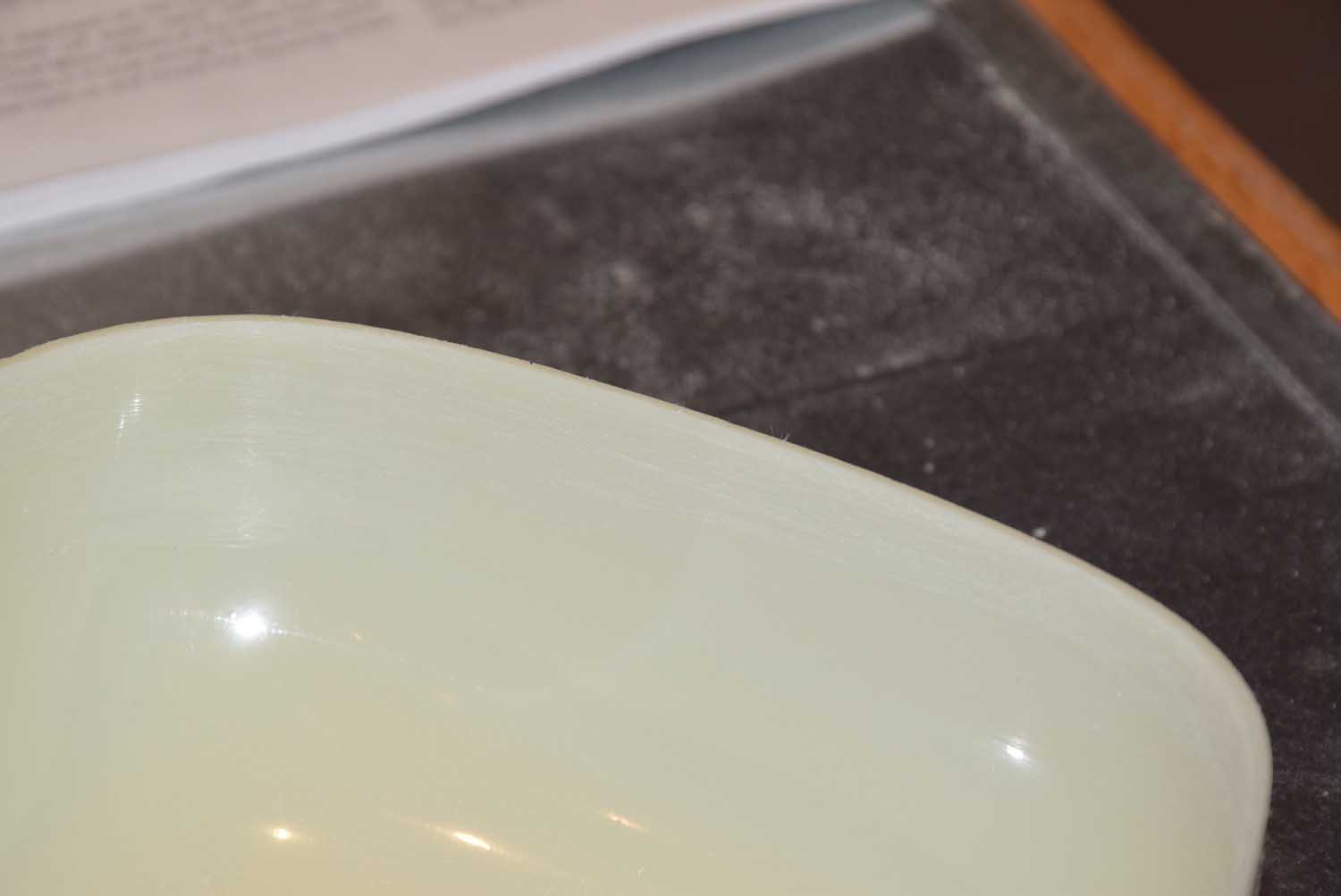
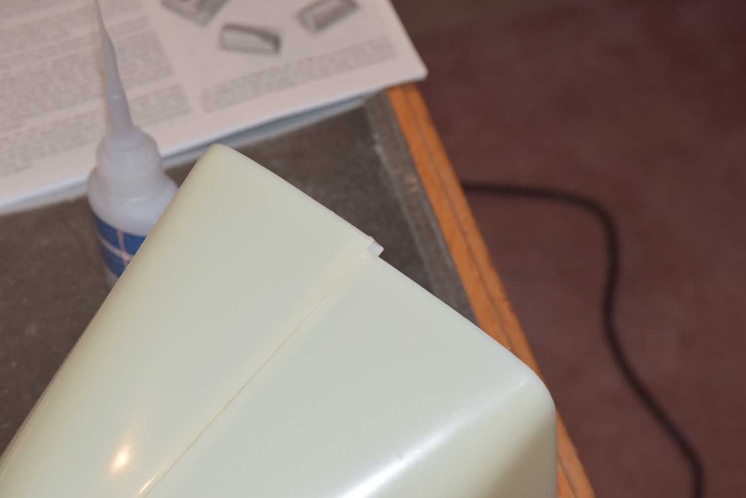
Glue the two cowl halves together using the provided plastic strip and thin CA. Roughen up the inside of the cowl where the bead of glue will be applied helps the CA glue adhere much better than on a smooth surface.
-
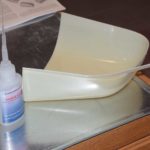
- start at one end gluing your way around
-
- roughen up the smooth edges of the cowl
-
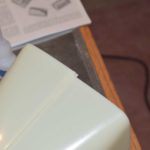
- a little extra over lap… can be sanded smooth later.
Next, determine where you want the prop hub to come through the front of the cowl. Use a hole saw to make a nice clean hole. Clean up the edges by hand and some 120 grit sand paper.
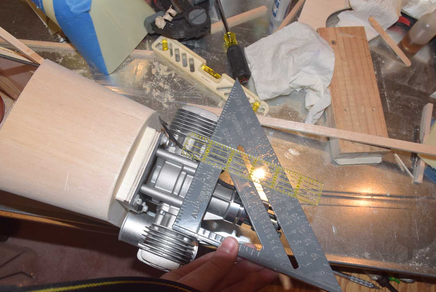
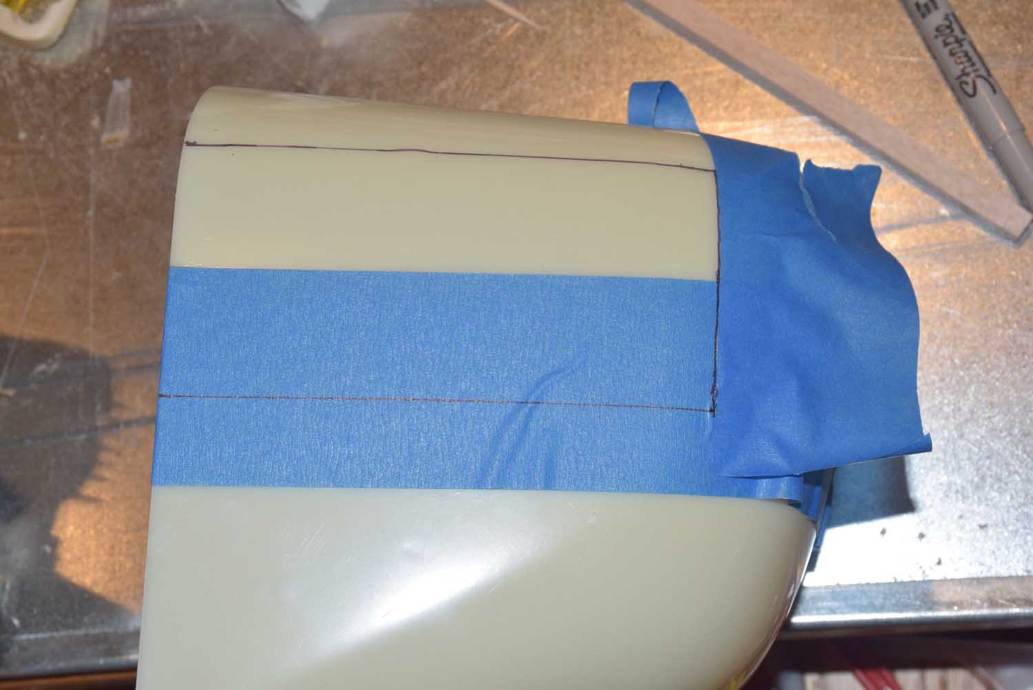
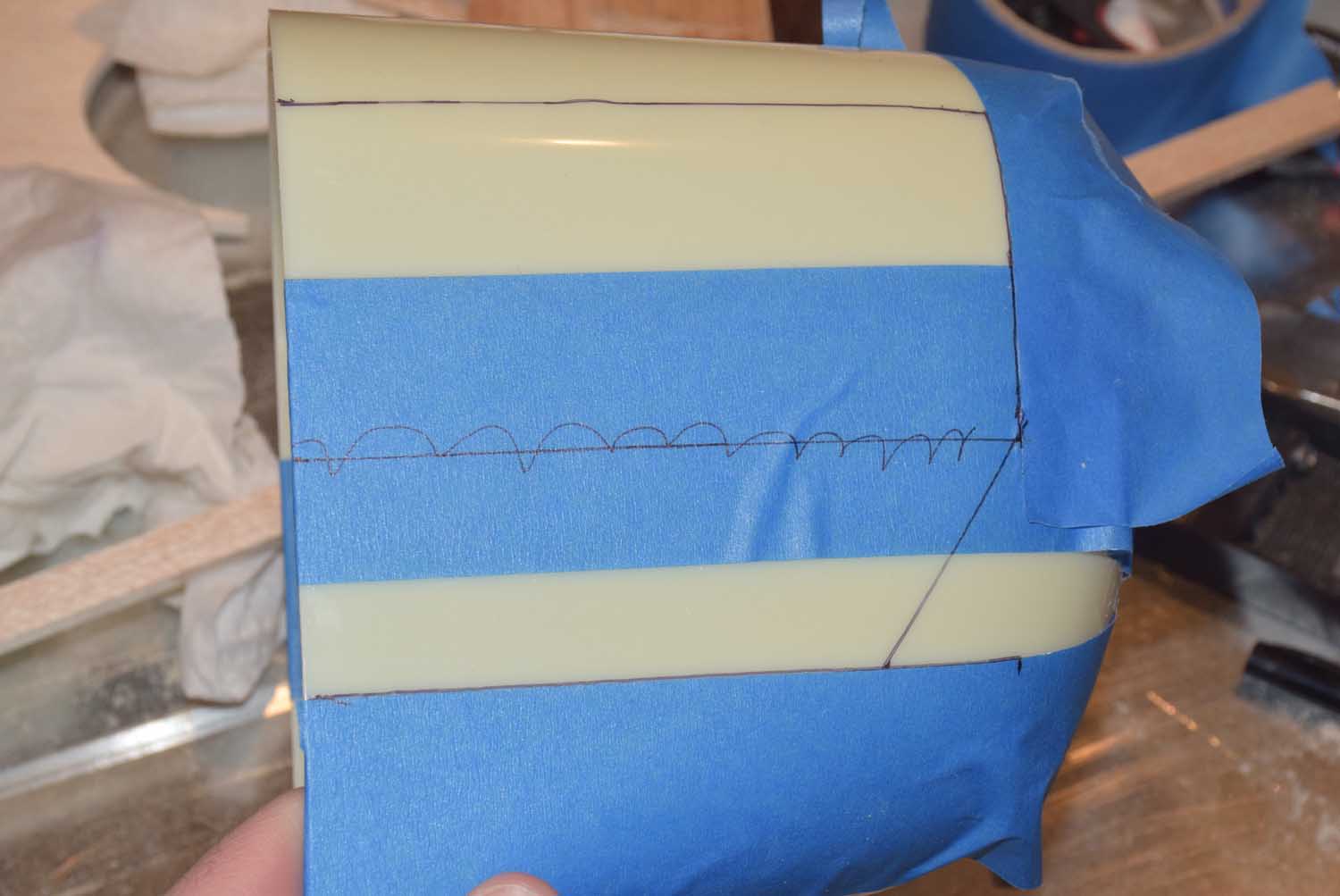
One each side of the cowl I placed a few strips of masking tape and using a ruler and a square I marked out the approximate cut lines of the shape of the cylinder and muffler locations on each side of the cowl. Be sure to take into account how much the cowl will “overlap” onto the nose of the airplane!
With the locations roughly marked out, I used a jigsaw to rough cut the cowl on the marked locations. The cutouts were quite rough but using a Dremel with a sanding drum you can smooth the edges quite nicely.
-
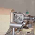
- engine mounted to firewal
-
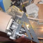
- using a square and ruler to get measurements
-
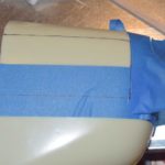
- top portion masked off
-
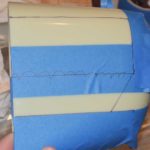
- mask off with tape according to measurements taken for muffler
-
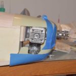
- rough cut but fits nicely!
The paint used to paint the cowl was from a spray can called VHT. This is an automotive based enamel paint that you can get in a spray can form. It sprayed nicely and evenly! This paint is heat and fuel resistant and has held up nicely so far! They have it available in a number of colors. The white color seemed to match fairly closely to the white covering I used on the rest of the plane. I also used their “bright red” color for the floats (covered in part 14 of this series)